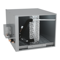
CHPE SERIES CASED HORIZONTAL COIL
INSTALLATION INSTRUCTIONS
IO-454A
12/2018
RECOGNIZE THIS SYMBOL AS A SAFETY PRECAUTION.
ATTENTION INSTALLING PERSONNEL:
Prior to installation, thoroughly familiarize yourself with this
Installation Manual. Observe all safety warnings. During in-
stallation or repair, caution is to be observed. It is your re-
sponsibility to install the product safely and to educate the
customer on its safe use.
Only personnel that have been trained to install, adjust, service
or repair (hereinafter, “service”) the equipment specified in
this manual should service the equipment. The manufacturer
will not be responsible for any injury or property damage
arising from improper service or service procedures. If you
service this unit, you assume responsibility for any injury or
property damage which may result. In addition, in jurisdictions
that require one or more licenses to service the equipment
specified in this manual, only licensed personnel should service
the equipment. Improper installation, adjustment, servicing
or repair of the equipment specified in this manual, or
attempting to install, adjust, service or repair the equipment
specified in this manual without proper training may result in
product damage, property damage, personal injury or death.
INSTALLATION INSTRUCTIONS
© 2018
www.daikincomfort.com
Our continuing commitment to quality products may mean a change in specifications without notice.
5151 San Felipe St., Suite 500 • Houston, TX 77056
Index
1 Important Safety Instructions ............................................................... 2
2 Shipping Inspection.............................................................................. 3
2.1 Parts ........................................................................................................... 3
2.2 Handling..................................................................................................... 3
3 Codes & Regulations ............................................................................ 3
4 Replacement Parts............................................................................... 3
5 Pre-Installation Considerations ............................................................ 3
5.1 Preparation ................................................................................................ 3
5.2 System Matches ......................................................................................... 3
5.3 Clearances.................................................................................................. 4
6 Application Information ....................................................................... 4
6.1 Duct Flange Attachment ............................................................................ 4
7 Return Ductwork.................................................................................. 5
8 Refrigerant Piping Work ....................................................................... 5
8.1 Tubing Size/Length..................................................................................... 5
8.2 Cut Off the Spin Closure ............................................................................. 6
8.3 Disconnect Internal Control Wiring ........................................................... 6
8.4 Connect Piping ........................................................................................... 6
8.5 Re-assemble the Coil and Controls ............................................................ 7
9 Sealing Along The Panel Gap .............................................................. 8
10 Drain Piping Work .............................................................................. 8
11 Electrical Wiring Work ....................................................................... 9
11.1 General Instructions................................................................................. 9
11.2 Wiring Sizing ............................................................................................ 9
11.3 Safety Device.......................................................................................... 10
11.4 Transformer Installation ........................................................................ 10
11.5 How To Install The Transformer ............................................................. 10
11.5.1A Installation Bracket - “A” .................................................................. 11
11.5.1B Installation Bracket - “B” .................................................................. 11
11.5.1C No Bracket Installation ..................................................................... 12
11.6 Wiring Transformer and PCB ................................................................. 13
12 ComfortNet™ System Trademark .......................................................13
12.1 Overview ................................................................................................ 13
12.2 Thermostat Wiring................................................................................. 13
12.3 Two-Wire Outdoor and Four-Wire Indoor Wiring.................................. 14
13 Miscellaneous Start-Up Checklist .......................................................14
14 Troubleshooting ................................................................................14
14.1 Electrostatic Discharge (ESD) Precautions ............................................. 14
14.2 Diagnostic Chart .................................................................................... 14
14.3 Fault Recall............................................................................................. 15
14.4 Network Troubleshooting ...................................................................... 15
14.5 System Troubleshooting......................................................................... 15
Communications Troubleshooting Chart ...................................................16
Troubleshooting .......................................................................................17
7-Segment LED Codes ...............................................................................17
Setting the Mode Display .........................................................................18
Wiring Diagram ........................................................................................20
Homeowner’s Rountine Maintenance .......................................................21
Cancer and Reproductive Harm -
www.P65Warnings.ca.gov
PROP 65 WARNING
FOR CALIFORNIA CONSUMERS
0140M00513-A