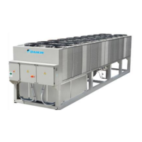
This document describes the CLIC STAND ALONE Series Air-Cooled Scroll Compressor Chiller Water Generator Unit from Clima-Flex, a member of the Daikin group. It serves as an Installation, Operation, and Maintenance Manual, providing comprehensive details for the 25 TR model, which uses HFC-410A refrigerant and operates on 50/60 Hz power.
Function Description:
The CLIC STAND ALONE Series chillers are self-contained, complete, and automatic air-cooled chilled water generators designed for outdoor installation. They are fully assembled, factory-wired, charged, and tested units. The electrical control center integrates all operating controls and equipment protection necessary for reliable automatic operation, housed within a weatherproof control panel. These units are designed to meet diverse project needs, utilizing intelligent process controllers and smart temperature sensors for maximum performance and energy savings. The system automatically adjusts its operating mode to maintain optimal conditions, ensuring ease of operation.
Important Technical Specifications:
The nomenclature for the CLIC series, exemplified by "CLIC-300-VL-C-1-A-N-D-F-M-M-N-N-0-2-S-N-D-N-4-C-0", decodes various specifications:
- Capacity (BTU): Ranges from 300 to 300,000.
- Air Discharge: Vertical Large (VL).
- Operation: Available for Cooling Only (C) or Heat Pump (H).
- Units: Can be Stand Alone (1) or combined in multiple units (up to 10).
- Condenser Fan: Axial Fixed (A).
- Anticorrosion: Options include Coat in Condenser (C), Coat in Components (I), Total Coating (M), or None (N).
- Voltage: Available in 208-230/3/60 (C) or 460/3/60 (D).
- Compressor: Fixed (F), Inverter (V), or Tandem (T).
- Condenser: Microchannel (M) or Cu-Al (C).
- Refrigerant: R410-A (4).
- Single Skid: With base (O) or N/A (N).
- Packaging: Domestic (D) or International (I).
- Hydraulic Connection: Not included (N) or Yes included (Y).
- Electrical Connection: Multipoint (M) or Single Point (S).
- Pipe: Available in 6" (6).
- Grills: Painted Grill (1) or N/A (0).
- Free Cooling: No (N).
- Heat Recovery: N/A (N) or Heat recovery (R).
- Protocol: Modbus (M) or BACnet IP (B).
For the 25 TR model, the refrigerant charge is 1 x 21 lbs (1 x 9.5 kg) of R410A. The evaporator pressure drop at 60 GPM is 34.01 ft WG for a 6" pipe size.
Operating and Standby Limits:
- Maximum standby ambient temperature: 130°F (54°C).
- Maximum operating ambient temperature: 105°F (41°C).
- Minimum operating ambient temperature (standard control): 32°F (0°C).
- Outgoing chilled water temperature: 40°F to 65°F (4°C to 18°C).
- Outgoing chilled fluid temperatures (with antifreeze): 15°F to 65°F (-9°C to 18°C).
- Maximum evaporator inlet fluid temperature: 81°F (27°C).
- Maximum non-operating evaporator inlet fluid temperature: 100°F (38°C).
Usage Features:
- Flexibility: Units feature intelligent processors and sensors for optimal temperature control. They can be coupled for tandem installations, combining up to 10 modules to meet various load variations, with capacities ranging from 25 to 250 tons.
- Communication: Units can be controlled in tandem mode or connected to a central control unit via a 7" color touch screen. They support Modbus and BACnet protocols. The control system monitors programmable variables, refrigeration cycle alarms, electrical system status, and external factors like fire or flood (optional sensors).
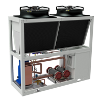
- Installation: Designed for easy installation with screw connections for water piping on either side. A rigid base balances unit weight, and lifting eyes are provided for safe handling. Minimum clearances are specified for optimal airflow and performance.
- Cold Water Piping: Requires a cleanable filter at the evaporator inlet (within 1,500 mm of connection, no solder between filter and evaporator) to prevent damage. A water flow switch is essential to prevent evaporator freezing under low or no flow conditions. Drain and vent connections are needed for brazed plate evaporators.
- Evaporator Freeze Protection: Units come with insulation. For sub-zero temperatures, recommendations include draining lines, adding glycol (approximately 10°F below minimum design ambient temperature), insulating exposed piping, or using thermostatically controlled heat tape.
- Electrical Connection: Units can be ordered with standard multi-point or optional single-point power connections. Wiring must comply with local and national codes (NEC®). Voltage unbalance should not exceed 2%. A properly installed and fully synchronized automatic transfer switch is required for generator power.
- Microchiller Controller: Uses Carel's µChiller solution for managing chillers and heat pumps. It supports electronic expansion valves (ExV) and brushless BLDC compressors for high efficiency. A user terminal allows wireless connectivity via mobile devices using the CAREL "APPLICA" app.
- VDF Compressor Controller: Features an LCP (Local Control Panel) with a graphical display for status, operator data, and text messages. Navigation keys allow access to menus and parameter settings. Local control keys (Hand on, Off, Auto on, Reset) provide direct control over the compressor.
Maintenance Features:
- Ease of Maintenance: Simple design ensures easy access to major components by opening service panels. The control section provides detailed failure causes for accelerated troubleshooting.
- Scheduled Maintenance: Routine checks are recommended during initial operation and periodically thereafter. A maintenance schedule is provided, including:
- Hydraulic Maintenance: Monthly cleaning of the hydronic circuit filter, visual inspection of water pipes for leaks, and annual replacement of water in the hydronic circuit.
- Electrical Maintenance: Quarterly re-tightening of electrical panel connectors and terminals, monthly physical inspection of connectors and relays, quarterly amperage checks of electric motors, and bi-monthly checks for false contacts. Monthly cleaning of the electrical panel.
- Physical Inspection: Bi-monthly cleaning of the condenser with pressurized water, quarterly refrigerant pressure checks, quarterly inspection and cleaning of fan blades, quarterly compressor power consumption checks, monthly compressor oil inspection, bi-monthly review and cleaning of internal equipment, quarterly review of condensate drain line, and monthly review of alarm history.
- Compressor Maintenance: Regular inspections are crucial to ensure safety devices are operational, check for leaks, monitor current levels, confirm consistent operation, and keep the compressor clean.
- Electrical Terminals: Connections should be inspected and tightened regularly to prevent arcing stress. Disconnect main power before servicing.
- Condenser Maintenance: Primarily involves removing dirt and debris from fins and repairing any damage. For corrosive environments, regular fin cleaning is part of the maintenance program.
The manual emphasizes safety warnings, including lockout/tagout procedures, electrical shock dangers, static discharge precautions, and proper handling of refrigerants and oils. It also highlights the importance of qualified personnel for installation and maintenance.