Do you have a question about the Daikin EWAD620-C17C-SS and is the answer not in the manual?
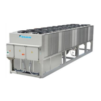
Provides an outline of relevant elements in EWAD-CJ air-cooled units.
Outlines the information contained in the chapter.
Details the benefits and characteristics of EWAD chillers.
Describes the advanced control logic of the MicroTech III controller.
Lists applicable laws and directives for EWAD unit manufacturing.
Details the CE marking and compliance with European directives.
Outlines the different efficiency versions available for EWAD units.
Describes the available sound level configurations for EWAD units.
Explains the model naming convention and its components.
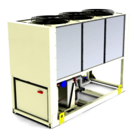
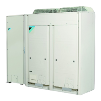
Describes the physical and functional characteristics of the unit.
Details the components of the refrigerant circuit.
Describes the power and control sections of the main panel.
Lists features of the built-in MicroTech III terminal.
Lists standard accessories provided with the basic unit.
Provides detailed technical specifications for EWAD~C-SS models.
Provides detailed technical specifications for EWAD~C-SL models.
Provides detailed technical specifications for EWAD~C-SR models.
Provides detailed technical specifications for EWAD~C-XS models.
Provides detailed technical specifications for EWAD~C-XL models.
Provides detailed technical specifications for EWAD~C-XR models.
Provides detailed technical specifications for EWAD~C-PS models.
Provides detailed technical specifications for EWAD~C-PL models.
Provides detailed technical specifications for EWAD~C-PR models.
Details electrical specifications for EWAD~C-SS models.
Details electrical specifications for EWAD~C-SL models.
Details electrical specifications for EWAD~C-SR models.
Details electrical specifications for EWAD~C-XS models.
Details electrical specifications for EWAD~C-XL models.
Details electrical specifications for EWAD~C-XR models.
Details electrical specifications for EWAD~C-PS models.
Details electrical specifications for EWAD~C-PL models.
Details electrical specifications for EWAD~C-PR models.
Cooling capacity and water flow data for EWAD-C-SS/SL models.
Correction factors based on condenser inlet air temperature.
Explains how to apply correction factors from tables.
Details control parameters for cooling water systems.
Details control parameters for cooled water systems.
Details control parameters for heated water systems.
Correction factors for evaporator fouling.
Correction factors based on altitude.
Recommended glycol percentages for low water temperatures.
Recommended glycol percentages for low air temperatures.
Correction factors for low evaporator leaving water temps.
Explains how to use correction factors for water/glycol mixtures.
Displays the operating range for EWAD-C units.
Specifies minimum and maximum evaporator water temperature differences.
Evaporator pressure drops for EWAD-C-SS/SL models.
Evaporator pressure drops for EWAD-C-SR models.
Evaporator pressure drops for EWAD-C-XS/XL models.
Evaporator pressure drops for EWAD-C-XR models.
Evaporator pressure drops for EWAD-C-PS/PL models.
Evaporator pressure drops for EWAD-C-PR models.
Discharge head curves for water pump kits.
Instructions for ensuring stability during shipping.
Manufacturer's disclaimer for improper installation.
General safety warnings for installation activities.
Safety warnings regarding lifting and handling.
Procedures for safely moving and lifting the machine.
Guidelines for proper unit placement and foundation requirements.
Minimum clearance requirements for correct ventilation and maintenance.
Notes on installation clearance and environmental factors.
Advice on isolating the machine to control sound levels.
Design considerations for water piping systems.
Provides dimensional data for 2-circuit EWAD-C models.
Provides dimensional data for 3-circuit EWAD-C models.
Cautionary notes and general electrical connection guidelines.
Lists necessary electrical components for installation.
Details power and interface connection wiring procedures.
Instructions for connecting the electrical power supply.
Information on the auxiliary control circuit transformer.
Describes the function of electrical heaters for evaporator and compressor.
Details the electrical supply for optional pump kits.
Explains how the microprocessor controls water pumps.
Wiring instructions for connecting alarm relays.
Wiring for remote unit on/off control.
Wiring for the double setpoint function.
Wiring for optional external water setpoint reset.
Explains capacity limitation via external signals or current absorbed.
Outlines operator duties and training requirements.
Describes the main components of the air-condensation chiller.
Explains the standard refrigeration cycle of the unit.
Explains the refrigeration cycle with partial heat recovery.
Highlights partial heat recovery operational limitations and requirements.
Illustrates and explains the single-screw compressor's operation.
Explains how compressor capacity is controlled.
Describes the operating diagram of the non-modulating box.
Lists the topics covered in the wiring diagrams chapter.
Explains symbols used in the wiring diagrams.
Lists and describes items used in wiring diagrams.
Details connections for digital input terminals.
Details connections for digital output terminals.
Details connections for analog input terminals.
Provides detailed information on unit functions and controls.
Outlines the chapter's content on controller and software functions.
Describes the overall controls architecture and module connections.
Lists topics related to customer interfaces.
Lists topics covered in display and keypad section.
Provides a general description of the control panel.
Illustrates the layout of the controller interface.
Explains system addresses and configuration for expansion boards.
Lists communication modules for BMS interface.
Provides a general description of the controller screen layout.
Lists and describes various set points for unit operation.
Provides detailed information on unit functions and controls.
Lists the topics covered in the unit functions chapter.
Explains how to start and stop the unit using set points and inputs.
Details how unit operating modes are determined by set points and inputs.
Describes the three possible states of unit control: Off, Auto, and Pumpdown.
Explains how displayed unit status is determined by various conditions.
Details the adjustable timer limiting chiller restarts in Ice mode.
Explains the control states and staging logic for evaporator pumps.
Outlines different pump configurations and staging logic.
Outlines conditions for enabling and applying noise reduction features.
Explains how the base LWT target is selected and reset.
Details how unit capacity is controlled in Cool mode.
Defines compressor staging order based on starts and run hours.
Explains compressor loading in Ice mode.
Defines the sequence for loading and unloading compressors.
Explains conditions that override automatic capacity control in COOL mode.
Lists topics covered in the circuit functions chapter.
Defines conditions for circuit availability, starting, and stopping.
Describes the displayed status of a circuit based on operational conditions.
Details compressor operation, cycle timers, and capacity control.
Explains control logic for saturated condenser temperature and fan staging.
Describes EXV operation modes and control logic.
Explains the activation and deactivation criteria for the economizer.
Outlines the conditions for activating and deactivating liquid injection.
Provides general guidance for identifying and addressing faults.
Explains alarm and event logging for chiller operation.
Lists alarms that cause a unit shutdown.
Describes the PVM/GFP fault, its triggers, and actions.
Details the Evap Water Flow Loss alarm, triggers, and reset conditions.
Explains the Evap Water Freeze alarm and its reset conditions.
Describes the Evap Water Inverted alarm and its triggers.
Details the Evap LWT Sens Fault alarm and its reset conditions.
Describes the AC Comm Fail alarm for I/O module communication issues.
Details the OAT Sensor Fault alarm and its reset conditions.
Describes the External Alarm triggered by an external input.
Explains the Emergency Stop Alarm when the input is open.
Lists unit events logged with timestamps.
Details the EWT Sensor Fail event and its reset condition.
Describes the External Event triggered by an external input.
Explains the Low Ambient Lockout triggered by low OAT.
Lists alarms requiring circuit shutdown.
Describes the PVM/GFP Fault alarm for circuits.
Details the Evap Press Low alarm and its freezestat logic.
Describes the LowPressStartFail alarm for circuit startup.
Details the Mech Low Pressure Sw alarm.
Explains the Cond Pressure High alarm.
Describes the Low Pressure Ratio alarm.
Details the Mech High Pressure Sw alarm.
Describes the Disc Temp High alarm.
Details the Oil Pres Diff High alarm.
Describes the Starter Fault alarm.
Details the Motor Temp High alarm.
Describes the LowOATRestart Fail alarm.
Details the NoPressChgAtStrt alarm.
Describes the No Press At Start alarm.
Details the CC Comm Fail alarm.
Describes FC Comm Fail alarms for circuits 1 and 2.
Details FC Comm Fail alarm for circuit 3.
Describes FC Comm Fail alarm for circuit 4.
Details FC Comm Fail alarms for circuits 3 and 4.
Describes EEXV Comm Fail alarms.
Details the EvapPressSensFault alarm.
Describes the CondPressSensFault alarm.
Details the OilPressSensFault alarm.
Describes the SuctTempSensFault alarm.
Details the DiscTempSensFault alarm.
Describes the MotorTempSensFault alarm.
Lists events that limit circuit operation.
Explains the EvapPress Low Hold event.
Details the EvapPressLowUnload event.
Explains the CondPressHigh Hold event.
Details the CondPressHighUnload event.
Describes the Pumpdown Fail alarm.
Explains the Run Power Loss alarm.
Describes how alarms are stored in active and history buffers.
Details how events are logged with timestamps and descriptions.
Provides information on input and output channel configurations.
Lists analog and digital I/O for the main board controller.
Details analog and digital I/O for compressor expansion modules.
Lists analog and digital I/O for EXV expansion modules.
Details digital I/O for fan modules circuits 1 & 2.
Lists digital I/O for fan module circuit 3.
Details digital I/O for fan module circuit 4.
Lists digital outputs for fan module circuits 3 & 4.
Details analog and digital I/O for unit alarm and limiting.
Outlines the topics related to software programming.
Details the process of programming controllers using an SD card.
Outlines the procedure for protecting the compressor from evaporator damage.
Provides a step-by-step procedure to protect the compressor from damage.
Outlines the procedure for clearing the refrigerant circuit.
Details the procedure to clean the refrigerant circuit after evaporator damage.
Introduces the troubleshooting chart.
Lists possible causes and corrective steps for compressor not running.
Troubleshooting steps for overload relay or breaker issues.
Troubleshooting steps for compressor noise or vibration.
Troubleshooting steps for compressor loading or unloading issues.
Troubleshooting steps for high discharge pressure issues.
Troubleshooting steps for low discharge pressure.
Troubleshooting steps for low suction pressure.
Troubleshooting steps for high suction pressure.
Explains the importance of commissioning and test runs.
Outlines checks to perform before every test run.
Provides a checklist for pre-start commissioning.
Lists general checks to be performed before unit operation.
Details checks related to water piping systems.
States that the chapter covers typical operating data.
Provides typical operating data for different efficiency levels.
Explains the importance of preventive maintenance.
Groups maintenance into system checks and standard checks.
Lists safety precautions for maintenance activities.
Covers routine inspections and checks for system performance.
Details recommended checks for compressor performance and wear.
Provides information on compressor oil and lubrication requirements.
Shows the schedule for ordinary maintenance activities.
Details the procedure for replacing filter dryer cartridges.
Provides procedures for oil filter replacement.
Important notes and warnings regarding refrigerant handling and charging.
Step-by-step guide for replenishing refrigerant.
Describes the function and location of various sensors.
| Model | EWAD620-C17C-SS |
|---|---|
| Category | Chiller |
| Type | Air-Cooled Screw Chiller |
| Cooling Capacity | 620 kW |
| Refrigerant | R-134a |
| Power Supply | 400V/3Ph/50Hz |
| Water Inlet Temperature | 12°C |
| Water Outlet Temperature | 7°C |
| Weight | 3500 kg |