EasyManua.ls Logo

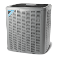
Daikin ComfortNet DZ16TC0361CA User Manual

Daikin ComfortNet DZ16TC0361CA
101 pages
To Next Page IconTo Next Page
Page #1 background imageLoading...
Page #1 background image
1
Service Instructions
ComfortNet™
DX16TC & DX18TC Condensing Units,
DZ16TC & DZ18TC Split System Heat Pumps
with R-410A Refrigerant
Blowers, Coils, & Accessories
This manual is to be used by qualied, professionally trained HVAC technicians only. Goodman
does not assume any responsibility for property damage or personal injury due to improper
service procedures or services performed by an unqualied person.
Copyright © 2015-2020 Daikin Manufacturing Company, L.P.
RSD6200007r21
March 2020

Table of Contents

Question and Answer IconNeed help?

Do you have a question about the Daikin ComfortNet DZ16TC0361CA and is the answer not in the manual?

Daikin ComfortNet DZ16TC0361CA Specifications

General IconGeneral
Model NumberDZ16TC0361CA
CategoryAir Conditioner
BrandDaikin
SeriesComfortNet
TypeSplit System
Cooling Capacity (BTU)36000
SEER Rating16
SEER16
Energy Efficiency Ratio (EER)12.5
HSPF9.5
RefrigerantR-410A
Voltage208/230
Phase1
Warranty12 years
Voltage (V)208/230V

Summary

Service Instructions

ComfortNet™ Condensing Units and Heat Pumps

Details on DX16TC/DX18TC condensing units and DZ16TC/DZ18TC heat pumps with R-410A.

Important Information - Safe Refrigerant Handling

Safe Refrigerant Handling Guidelines

Guidelines and warnings for safe handling of refrigerants, including hazards and precautions.

System Operation - Cooling and Heating

Cooling Cycle Operation

Details the refrigerant flow and component operation during the cooling cycle.

Heating Cycle Operation

Explains the refrigerant flow and component operation during the heating cycle.

System Operation - Defrost Cycle

System Operation - Cycle Diagrams

System Operation - Valve Assembly

Troubleshooting Chart

Possible Causes and Test Methods

A detailed chart linking symptoms to possible causes and recommended test methods for troubleshooting.

S-1 Checking Voltage

S-2 Checking Wiring

CTK04 Standard Wiring Scheme

CTK04 Alternate Wiring Scheme

Network Troubleshooting

Communications Troubleshooting Chart

7 Segment LED Display Codes

PCBJA101- PCBJA102 Air Handler Diagnostic Codes

PCBJA101- PCBJA102 Air Handler Diagnostic Codes (Cont.)

PCBJA104 Air Handler Diagnostic Codes

PCBJA104 Air Handler Diagnostic Codes (Cont.)

S-4 Checking Transformer And Control Circuit

S-8A Checking Unitary (UC) Control Compressor Contactor/Relay Contacts

S-9 Checking High and Low Voltage to ECM Motor

S-10A Copeland Comfort Alert™ - Unitary (UC) Control Diagnostics

Unitary Diagnostic Codes (ComfortNet™)

Unitary Diagnostic Codes (ComfortNet™) (Cont.)

Unitary Diagnostic Codes (DS1/DS2)

Unitary Diagnostic Codes (ComfortNet™) (Cont.)

Unitary Diagnostic Codes (ComfortNet™) (Cont.)

Continues the table of unitary diagnostic codes, covering high line voltage and low pilot voltage faults.

S-12 Checking High Pressure Control

S-13 Checking Low Pressure Control

S-15 Checking Capacitor

S-15B Capacitance Check Using a Digital Multi-Meter

S-16G Checking Emerson Ultratech™ ECM Motors

Emerson UltraCheck-EZ™ Diagnostic Tool

Electrical Checks - High Voltage Power Circuits

Electrical Checks - Low Voltage Control Circuits

Motor Control/End Bell Checks

S-16H ECM CFM Adjustments DVPTC/MBVC

MBVC Airflow Table and Dip Switch Settings

Dip Switches - Cooling Airflow and Airflow Adjust Taps

Cooling/Heat Pump Airflow Tables

Electric Heat Airflow Table

READY DVPTC AIRFLOW TABLES

DVPTC Electric Heat Airflow Tables

S-17 Checking Compressor

S-17A Resistance Test

S-17B Ground Test

S-17C Unloader Test Procedure

S-17D Operation Test

S-21 Checking Reversing Valve and Solenoid

S-24 Testing Defrost Control

S-26 Testing Temperature Sensors

Electric Heater Checks

Data Line Voltage Troubleshooting and Bias Switches

Sequence of Operation: DVPTC/MBVC with DX**TC Condenser and CTK0* Communicating Thermostat

Sequence of Operation (Cont.)

4.0 Defrost Operation

5.0 Emergency Heat Operation

S-61A Checking Heater Limit Control(s)

S-61B Checking Heater Fuse Link

S-62 Checking Heater Elements

S-101 Leak Testing (Nitrogen or Nitrogen-Traced)

S-102 Evacuation

S-103 Charging

S-104 Checking Compressor Efficiency

S-106 Overfeeding

S-107 Underfeeding

S-108 Superheat

S-109 Checking Subcooling

S-112 Checking Restricted Liquid Line

S-113 Overcharge of Refrigerant

S-114 Non-Condensables

Checking Compressor Efficiency

Pressure vs. Temperature Chart (R-410A)

Required Liquid Subcooling Temperature Chart

S-115 Compressor Burnout

S-203 Single Piece Air Handler External Static Pressure

S-203A Two Piece Air Handler External Static Pressure

DV**PTC/MBVC Wiring Diagram

DX16TC Wiring Diagram

DX18TC Wiring Diagram

DZ18TC Wiring Diagram

Related product manuals