4 Installation
Installation Manual
11
D2CNL024A1AA
Wall-mounted condensing boiler
3P469346-12R – 2021.09
For use of any additive in the central heating system, please refer to
the instructions of their manufacturers to ensure above functionality
and compatibility.
Water softening for domestic water circuit is recommended if
hardness of supply water is higher than 20°fH, in order to prevent
damage on boiler.
WARNING
Mixing inappropriate additives with the central heating
circuit water can result in efficiency loss in the boiler or
damage to the boiler and the other central heating circuit
elements. Daikin accepts no liability for any such damage
or ineffectiveness caused by using inappropriate additive.
4.6 Underfloor heating requirements
Underfloor heating systems apparently require higher flow rate and
lower ΔT. This boiler can be connected to an underfloor heating
system without use of a second pump and low loss header because
of its high pump capacity. Direct connection is possible when the
system is well designed and pressure loss is low enough.
When the boiler is connected to underfloor heating installation, the
maximum central heating set temperature must be limited to 50°C
and the pump operation temperature difference must be adjusted to
10Kelvin in the service settings menu. To change this setting, refer
to the servicing instructions.
WARNING
Make sure parameter changes explained above are done
to avoid discomfort of the user.
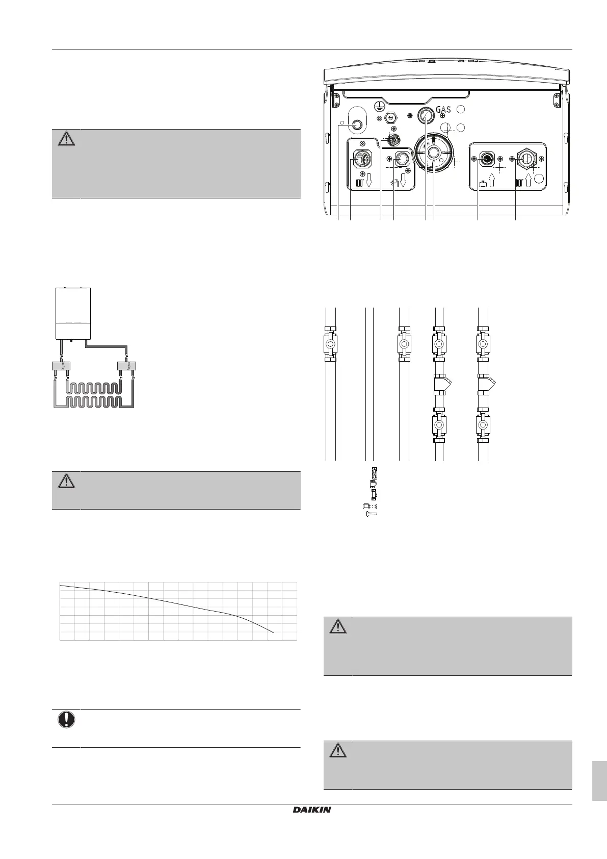
4.7 Residual pump lift graph
The residual pump lift graph shows the amount of pump lift (mbar)
that remains for the central heating circuit.
00
0 100 200 300 400 500 600 700 800 900 1000 1100 1200 1300 1400 1500 1600
A Residual pump lift (mbar)
B Flow (l/h)
4.8 Connections
NOTICE
During installation, do not loosen or remove any screw
from bottom plate.
4.8.1 Piping connections
Below, find the piping connections of the unit.
a Central heating return connection, 3/4"
b Domestic cold water inlet connection, 1/2"
c Condensate trap discharge
d Domestic hot water outlet connection, 1/2"
e Central heating supply connection, 3/4"
f Gas inlet connection, 3/4"
g Filling valve
h Safety valve discharge
Valve
Strainer
Tee connection
Double check valve + filling hose
Disconnector
a Isolation valve on domestic hot water supply pipe is
tentative
Isolation valves and strainers should be used just before the
appliance piping inlet as shown in figure above.
Ensure that necessary gaskets are placed.
4.8.2 Guidelines when connecting the gas
piping
WARNING
ONLY qualified persons are allowed to connect the gas
piping. The gas inlet pipe diameter MUST be selected
according to the applicable legislation, standards, and
regulations.
Connect the gas piping according to applicable legislation of the
country of destination and the regulations of the gas supply
company.
Connect the gas supply piping without tension to the gas pipe
connection ("Connection F", see "4.8.1Piping connections"[411]).
WARNING
After the gas connection is made, the gas line MUST be
tested for leakage while the gas line to the boiler is open
(see "5.2To check for gas leakage"[421]).