16
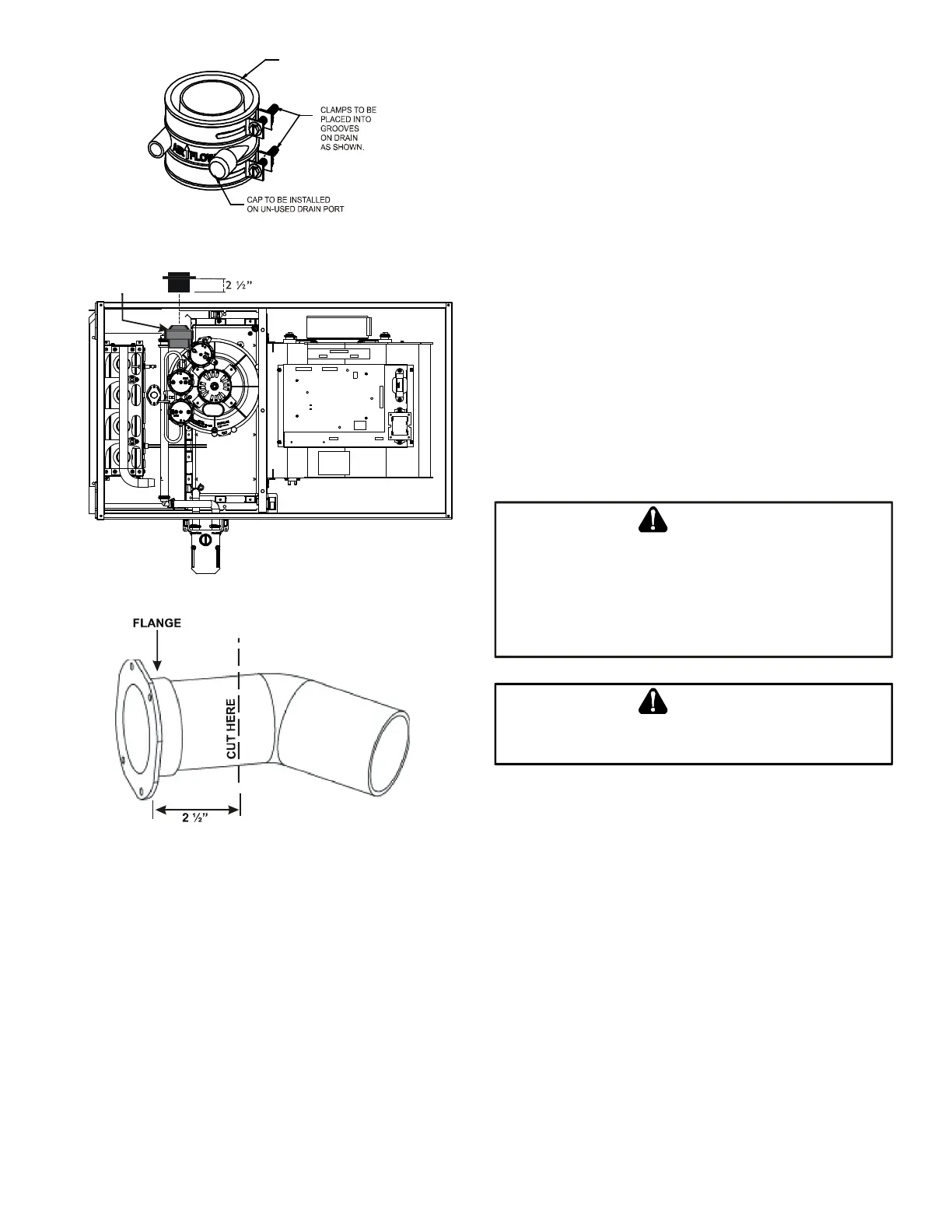
Insert flange. Cut 2 ½” long.
R 000142
F
1. Remove the four screws from the vent pipe ange
on top the furnace.
2. Remove the internal elbow, vent pipe & gasket.
3. Cut the internal vent pipe 2 1/2” from the ange.
Discard the un-anged section.
4. Remove the 3” plastic plug (in line with the inducer
outlet) and insert it in the space vacated by removal
of the internal vent pipe.
5. Install the RF000142 drain coupling with arrow
facing up, on the draft inducer outlet.
6. Insert the 2 ½” anged section of pipe with gasket
through the 3” hole and connect to RF000142 drain
coupling. Secure it with gear clamp provided.
7. Use the four self-tapping screws removed in step 1
to secure ange to cabinet.
8. Connect drain hose to the uncapped port on the
RF000142 coupling, refer to page xx, section
entitled “Horizontal Installation with Left Side Down
– Alternate” for drain connection details
When using the alternate venting location, either in
a horizontal left side down installation or a vertical
installation using down – venting, the alternate combustion
air opening can be used. A locating dimple is located on
the right side of the furnace cabinet. The locating dimple is
1-7/8” measured from the front edge of the cabinet in line
with the knock out.
To use the alternate combustion air location:
1. Remove screws and combustion air ange and
gasket from cabinet.
2. Insert the 3” cabinet plug from the drain bag
assembly in the unused combustion air hole.
3. Drill a pilot hole at the cabinet dimple (size dictated
by knockout tool used).
4. Use a knockout tool to create a 3” diameter hole.
5. Secure the combustion air ange & gasket to the
furnace cabinet using the self-tapping screws
removed in step 1.
T
HE
RUBBER
IS
NOT
TO
SUPPORT
A
LOAD
HEN
THE
RUBBER
IS
EXTERNALLY
TO
THE
CABINET
,
CARE
BE
TAKEN
TO
SUPPORT
-
SUPPLIED
VENT
/
,
AS
CAN
RESULT
IN
LEAKS
BODILY
INJURY
OR
DEATH
DUE
TO
EXPOSURE
TO
,
CARBON
E
B
E
SURE
NOT
TO
INTERNAL
OR
OTHER
AND
 Loading...


