Unit Piping - Condensate Drain Connection
WARNING
Drain pans must be cleaned periodically. Material in
uncleaned drain pans can cause disease. Cleaning
should be performed by qualified personnel.
The unit is provided with a condensate drain connection, a 3/4"
male NPT for 003–015 units and a 1" male NPT for 016–028
units. For proper drainage, level the unit and drain pan side to
side and install a P-trap.
Figure 7 shows the layout of the condensate drain connection.
The distance from the drain pan outlet to the horizontal run of
the P-trap should be a distance of twice the static pressure in
the drain pan.
Example: If the static pressure as measured in the drain pan
is 1.5", then the distance between the drain outlet and the
horizontal run should be 3".
Draining condensate directly onto the roof may be acceptable;
refer to local codes. Provide a small drip pad of stone, mortar,
wood, or metal to protect the roof against possible damage.
If condensate is piped into the building drainage system, pitch
the drain line away from the unit a minimum of 1/8" per foot.
The drain line must penetrate the roof external to the unit.
Refer to local codes for additional requirements. Sealed drain
lines require venting to provide proper condensate ow.
Periodically clean to prevent microbial growth/algae buildup
from plugging the drain and causing the drain pan to overow.
Clean drain pans to prevent the spread of disease. Cleaning
should be performed by qualied personnel.
Figure 7: Condensate Drain Connection
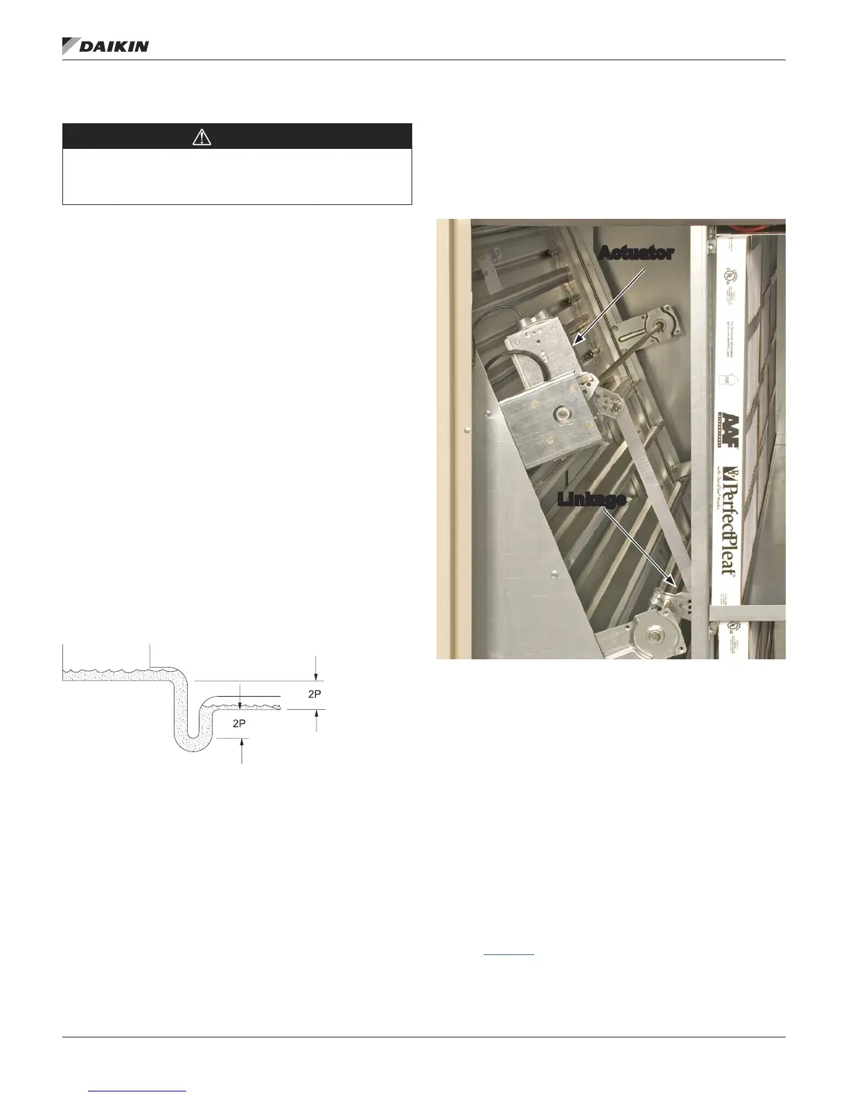
Damper Assemblies
The optional damper assemblies described in this section
are ordered with factory-installed actuators and linkages.
The following sections describe the operation and linkage
adjustment of the factory option.
Figure 8: Damper Assembly
Economizer Dampers
As the single actuator modulates, the outside air dampers
open, the return air dampers close, and the exhaust air exits
the unit through the gravity relief dampers.
The economizer comes with manually adjustable linkage (Figure
8). The damper is set so that the crank-arm moves through
a 90-degree angle to bring the economizer dampers from full
open to full close. Mechanical stops are placed in the crank-arm
mounting bracket. Do not remove stops. Driving the crank-arm
past the stops results in damage to the linkage or damper.
Outdoor Air Dampers (0% to 30%)
These dampers are intended to remain at a xed position during
unit operation, providing fresh air quantities from 0 to 30% of the
total system airow, depending on the damper setting.
The damper position may be set at the unit controller keypad
(refer to OM 1141 for further detail). During unit operation, the
damper is driven to the position set at the unit controller. During
the OFF cycle, the damper is automatically closed.
at the Drain Pan
Linkage
IM 1125-7 • REBEL ROOFTOPS 12 www.DaikinApplied.com
MeChanICal InsTallaTIon