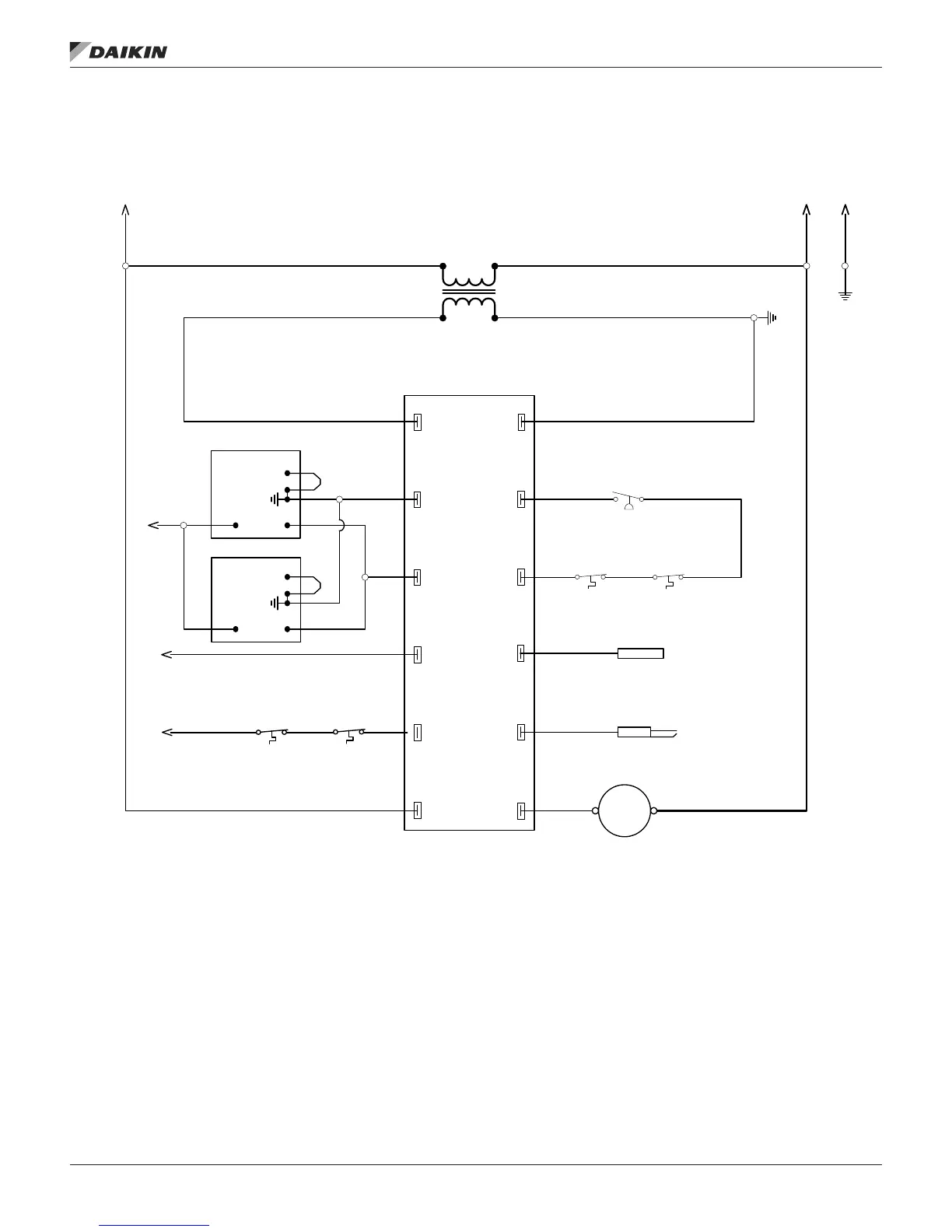
Figure 56: Typical 2 Stage Control Gas Furnace, 450/600 MBH — DPS 016–028 shown
L1
IND
COMX
MV
PS1
PS2
W
R
FS
HV
C
Hi-Limit
Switch
TS02
Aux Hi-Limit
Switch
TS01
Roll-out
Switch #1
TS03
Air Pressure Switch
PS01
Spark Igniter
SI01
Roll-out
Switch #2
TS04
MTR
24VAC
115VAC
C
HI
LO
remotely
mounted
602A
602B
TB10
604A
604B
614A
612A
TB10
612D
604A 608A
611C 611D
614B
614C
617B
620D
623A
617A
602C
620A
620B
620C
(Daikin P/N 910172859; includes ignitor and wire)
600
601
602
603
604
605
606
607
608
609
610
611
612
613
614
615
616
617
618
619
620
621
622
623
624
P1-1/L1 P1-2/L2
P1-3/GND
LED Diagnostic Information
Steady Off: No power or Control hardware fault
Steady On: Power applied, Control OK
1 Flash: Combustion fan motor energized, Pressure switch open
2 Flashes: Combustion fan motor off, Pressure switch closed
3 Flashes: Ignition lockout from too many trials
4 Flashes: Ignition lockout from too many flame losses within single call for heat
5 Flashes: Control hardware fault detected
TB10
101
T3
Class II
40VA
T01
TB10
102
TB10
GND
TB10
GND
611B
C
HI
LO
TB10
105
612C
612B
616A
103
104
611A
615A
2/A
1/A
R/A
Gas Safety Shutoff Valve #1
GSSV01
Gas Safety Shutoff Valve #2
GSSV02
602D
Inducer Fan Motor
IFM01
Flame Sensor
FS01
Ignition Module #1
IM01
UTEK 1016-575
Rebel C 450/600 MBH Gas Furnace Electrical Schematic
2 Stage Control
HW VR8305Q Vlv (for NG)
HW VR8205Q Vlv (for LPG)
HW VR8305Q Vlv (for NG)
HW VR8205Q Vlv (for LPG)
IM 1125-7 • REBEL ROOFTOPS 62 www.DaikinApplied.com
opTIonal gas heaT