unIT opTIons
Economizer Enthalpy Control
The economizer can be ordered with the optional differential
enthalpy control. With this option a solid-state humidity and
temperature sensing device is located in the return and
outdoor airstreams. These devices are labeled RAE and OAE
respectively. When the outdoor enthalpy is lower than the
return air enthalpy, the economizer operation will be initiated.
If the outdoor air enthalpy is higher than the return air, the
outdoor air damper position will be at the minimum setpoint.
See OM 1141 for further information on the economizer
operation.
External Time Clock
You can use an external time clock as an alternative to (or in
addition to) the MicroTech III controller’s internal scheduling
function. The external timing mechanism is set up to open and
close the circuit between eld terminals 101 and 102. When
the circuit is open, power is not supplied to binary input ID1.
This is the normal condition where the controller follows the
programmable internal schedule. When the circuit is closed,
power is fed to ID1. The MicroTech III controller responds
by placing the unit in the occupied mode, overriding any set
internal schedule.
Exhaust Fan Option
Economizer units may include exhaust fan options. For units
with CAV applications, the exhaust fans can be ordered as
staged control or they may be ordered with building pressure
control. The building pressure control option has an inverter
that runs the exhaust fan motors and is controlled by the static
pressure sensor number 2 (SPS2). The units are only available
with building pressure control on VAV units.
The exhaust fan motors are permanently lubricated and do not
require any additional periodic lubrication.
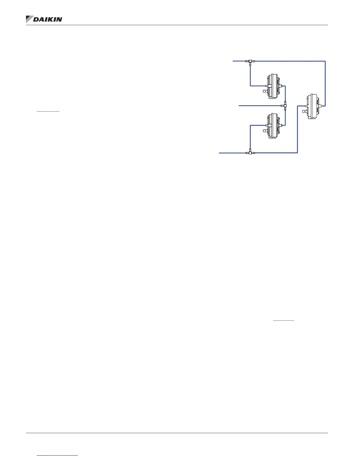
Proof-of-Airow and Dirty Filter Switch
The proof-of-airow switch (PC7) and the dirty lter switch
(PC5) are supplied on all CAV units. The tubing is installed
to the switches per Figure 70. The proof of airow switches
senses the pressure difference between the positive pressure
in the supply air fan compartment and the suction pressure
on the leaving air side of the lters. The differential pressure
is factory set for this switch. The dirty lter switch senses the
pressure difference across the lter; from the entering air side
of the lter to the leaving air side of the lters. The switch is
factory set at 1.0". When the pressure difference across the
lters is sensed at this value, the dirty lter alarm will appear
on the DDC controller.
Figure 70: Pressure Tubing Diagram
All VAV units also have the PC7 and PC5 switches as standard
(see Figure 70). These switches are tied into the Duct High
Limit switch (DHL) as shown in Figure 70.
The DHL is factory set at 4.0". When this differential pressure
is sensed the normally closed contacts will open on the switch
giving the DHL alarm at the unit controller.
Duct High Pressure Limit
The duct high pressure limit control (DHL) is provided on all
VAV units. The DHL protects the duct work, terminal boxes,
and the unit from over pressurization, which could be caused
by, for example, tripped re dampers or control failure.
The DHL control opens when the discharge plenum pressure
rises to 3.5" wc (872 Pa). This setting should be correct for
most applications and should not be adjusted.
If the DHL switch opens, digital input ID9 on the Unit Control
Board will be de-energized. The MicroTech III controller then
shuts down the unit and enters the Off-Alarm state. The alarm
must be manually cleared before the unit can start again.
Refer to the operation manual supplied with your unit for more
information on clearing alarms (refer to OM 1141).
TO SUPPLY
N PLENUM
HI LO
HI
LO
HI
PC7
PC5
DHL
AIR SIDE OF
THE FILTERS
TO LEAVING
AIR SIDE OF
THE FILTERS
IM 1125-7 • REBEL ROOFTOPS 76 www.DaikinApplied.com
unIT opTIons