Gas Heating Capacity Data
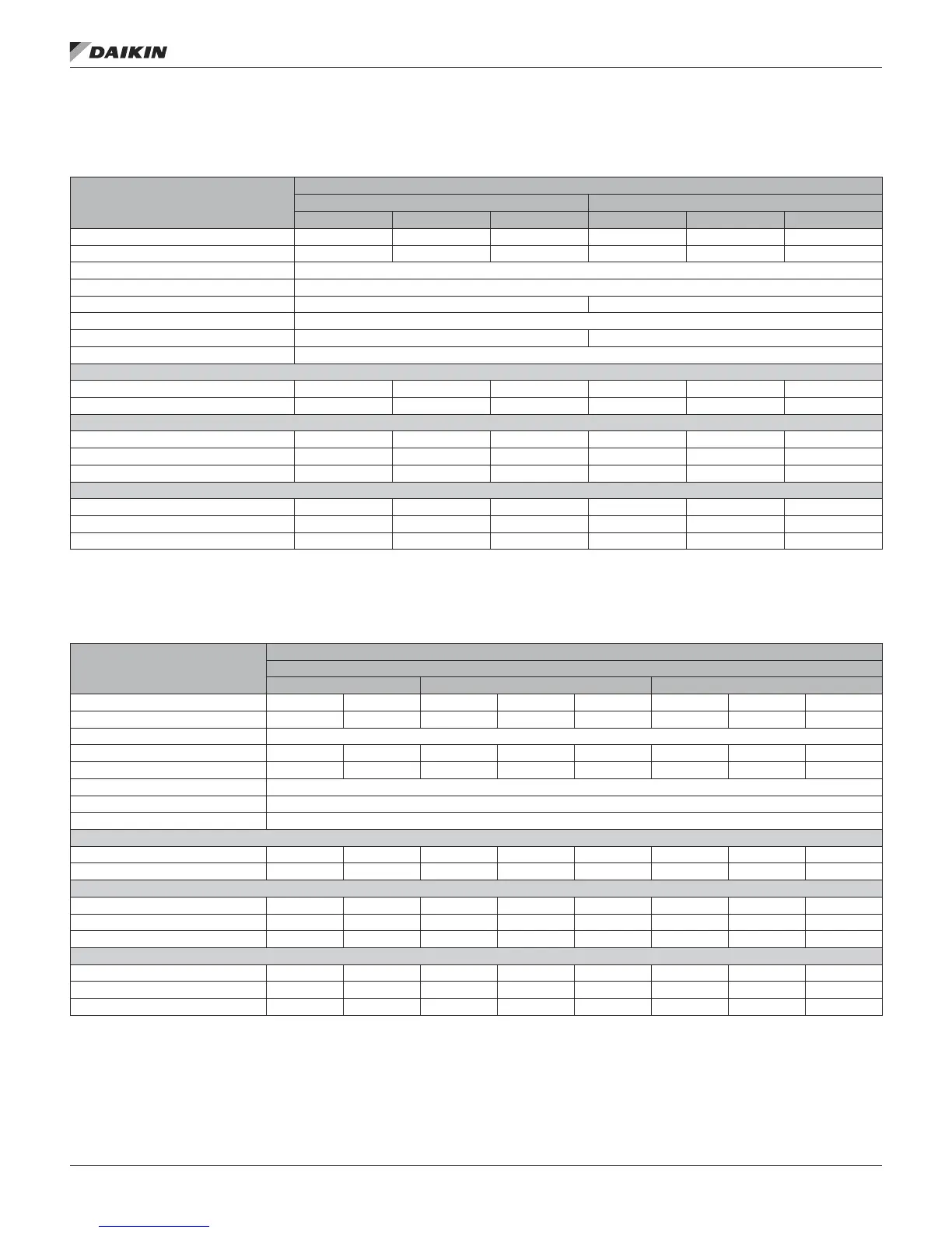
Table 14: DPS 003-015 Gas Heating Capacities
Data
Unit Size
003 - 006 007 - 015
Low Heat Med Heat High Heat Low Heat Med Heat High Heat
Heating Input (MBh) 80 120 160 200 300 400
Heating Output (MBh) 64 96 128 160 240 320
Steady State Efciency 80%
Number of Stages 2
Turndown
1
5:1 10:1
Maximum Temperature Rise
3
60/100
Gas Connection Size 1/2" 3/4"
Min/Max External Static Pressure 0.5"/2.5"
Gas Main Pressure
Natural Gas (in. wc) 7-14 7-14 7-14 7-14 7-14 7-14
Propane (in. wc) 12-14 12-14 12-14 12-14 12-14 12-14
Manifold Pressure Natural Gas (per gas valve)
Stage 1 (in. wc) 1.2 1.2 1.2 1.2 1.2 1.2
Stage 2 (in. wc) 3.2 3.2 3.2 3.2 3.2 3.2
Low re
2
0.4 0.4 0.4 0.4 0.4 0.4
Manifold Pressure Propane Gas (per gas valve)
Stage 1 (in. wc) 2.3 2.3 2.3 2.3 2.3 2.3
Stage 2 (in. wc) 10.0 10.0 10.0 10.0 10.0 10.0
Low re
2
N/A N/A N/A N/A N/A N/A
NOTE:
1. Modulating heat only.
2. Modulating heat not available with propane.
3. Aluminized steel 60°, Stainless steel 100°
Table 15: DPS 016–028 Gas Heating Capacities
Data
Unit Size
016 - 028
Low Heat Medium Heat High Heat
Heating Input (MBh) 300 300 450 450 450 600 600 600
Heating Output (MBh) 240 240 360 360 360 480 480 480
Steady State Efciency 80%
Control (stage/modulating) 2 Mod 2 4 Mod 2 4 Mod
Turndown 2:1 5:1 2:1 4:1 10:1 2:1 4:1 10:1
Maximum Temperature Rise 100
Gas Connection Size ¾"Ø
Min/Max External Static Pressure 0.5"/2.5" wc
Gas Main Pressure
Natural Gas (in wc) 7-14 7-14 7-14 7-14 7-14 7-14 7-14 7-14
Propane Gas (in wc) 12-14 12-14 12-14 12-14 12-14 12-14 12-14 12-14
Manifold Pressure Natural Gas (per gas valve)
Stage 1 (in wc) 0.88 0.88 0.88 0.88 0.88 0.88 0.88 0.88
Stage 2 (in wc) 3.5 3.5 3.5 3.5 3.5 3.5 3.5 3.5
Low Fire 0.88 0.26 0.88 0.88 0.26 0.88 0.88 0.26
Manifold Pressure Propane Gas (per gas valve)
Stage 1 (in wc) 2.5 2.5 2.5 2.5 2.5 2.5 2.5 2.5
Stage 2 (in wc) 10.0 10.0 10.0 10.0 10.0 10.0 10.0 10.0
Low Fire 2.5 0.74 2.5 2.5 0.74 2.5 2.5 0.74
opTIonal gas heaT
www.DaikinApplied.com 41 IM 1125-7 • REBEL ROOFTOPS