DPS 003–015 (only) Gas Furnace Ignition and Control Troubleshooting
Variable Furnace Controller
Daikin’s furnace controller is an electronic device that delivers
full control of the modulating furnace. Control includes
sequencing, ignition, safety, modulation of the control valve,
and the induced draft motor. Inputs to the furnace control board
are an a 0-10V signal. The analog signal will modulate the
burner down to 25% of full load. Safety inputs include pressure
line and electrical connection from the airow proong switch
and electrical connection from the rollout switches. Control
board outputs are to the igniter board, modulating gas valve,
and to the induce draft motor.
VB-1200 Trouble Shooting Guide
Modulating Furnace Diagnostics
The Rebel furnace control that operates the furnace has
built-in, self-diagnostic capability. The control continuously
monitors its own operation and the operation of the system.
The LED on the control indicates the current system state,
warnings, failures and test modes.
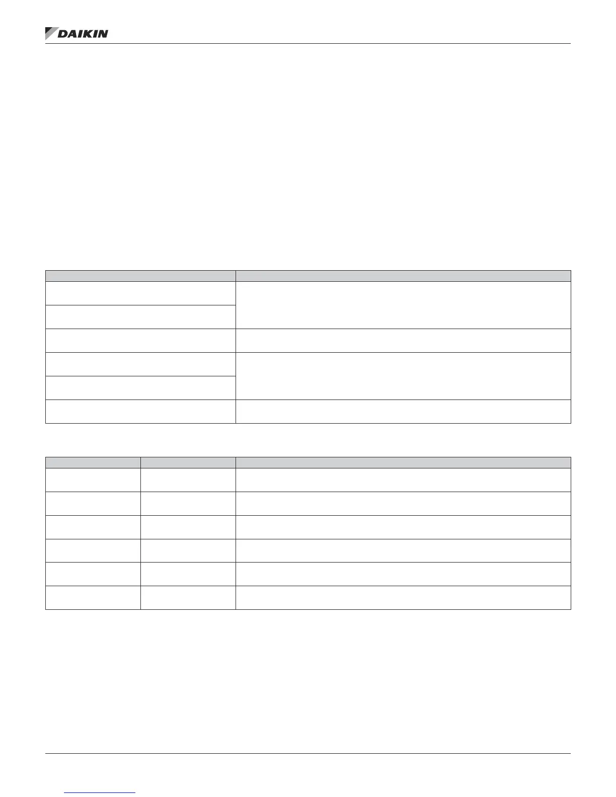
Table 22: Furnace I.D. Plug Information (Displayed on Power-up)
Display Information (example) Description
C
Furnace series or model name, for example, C cabinet series.
CAb
400
Furnace size in 1000’s of BTU, for example, 400 kBTU.
nAt or LP
Burner fuel type, for example, natural gas or LP.
6AS or LP
1.01
Software version, for example, v1.01
Table 23: Normal Furnace Operation
Display Information Mode Description
Off
OFF Mode System Idle - Control board has power, no faults found, no call for heat.
PVr
PURGE Mode
System is purging the heat exchanger – No gas on, no ame, inducer runs for the specied purge
timings. Purge cycles occur immediately before and after each burner operation.
I9n
IGNITION Mode
System is initiating burner operation – Igniter energized, modulating valve moved to ignition setting, gas
on. Maintained for the trial-for-ignition period and the ve second ame stabilization period.
HEA
WARM-UP Mode Period between Ignition and Run – System checks completed before modulation control begins.
rVn
RUN Mode Normal modulating operation.
rEt
Ignition Retry
System has had a failed ignition attempt or has lost ame during burner operation and is beginning
another ignition cycle.
IM 1125-7 • REBEL ROOFTOPS 54 www.DaikinApplied.com
opTIonal gas heaT