EasyManua.ls Logo

Daikin DZ18VC Series User Manual

Daikin DZ18VC Series
52 pages
To Next Page IconTo Next Page
Page #1 background imageLoading...
Page #1 background image
Our continuing commitment to quality products may mean a change in specications without notice.
© 2015 - 2016, 2018, 2020                  
19001 Kermier Rd., Waller, TX 77484
www.daikincomfort.com

The following symbols and labels are used throughout this
manual to indicate immediate or potential safety hazards. It
is the owner’s and installer’s responsibility to read and comply
with all safety information and instructions accompanying
these symbols. Failure to heed safety information increases
the risk of personal injury, property damage, and/or product
damage.
!
D
M



.
WARNING








I




.






UMP
-






UMP
-






















.
CAUTION

Always keep the unit upright; laying the unit on its side or top
may cause equipment damage. Shipping damage, and sub-
sequent investigation is the responsibility of the carrier. Verify
the model number, specications, electrical characteristics,
and accessories are correct prior to installation. The distributor
or manufacturer will not accept claims from dealers for trans-
portation damage or installation of incorrectly shipped units.



INSTALLATION INSTRUCTIONS
IOD-4016H
4/2020
Index
 1
 1
 2
 2
 2
 2
 3
 3
 5
 5
 5
 6
 11
 12
 16
 18
 24
 28
 30
WARNING


Cancer and Reproductive Harm -
www.P65Warnings.ca.gov
0140M00517-A
Question and Answer IconNeed help?

Do you have a question about the Daikin DZ18VC Series and is the answer not in the manual?
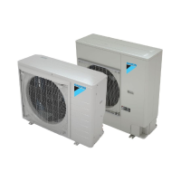
Daikin DZ18VC Series Specifications

General IconGeneral
TypeHeat Pump
RefrigerantR-410A
Energy Star CertifiedYes
Voltage208/230V
Phase1
Compressor TypeInverter
StagesVariable

Summary

Installation Instructions

Important Safety Instructions

Crucial safety information and hazard warnings related to electrical shock, explosions, and personal injury.

Shipping Inspection

Procedures for checking the unit upon delivery for damage and correct specifications.

Codes and Clearances

Codes & Regulations Compliance

Adherence to national and local installation codes and regulations.

Installation Clearances

Required spacing around the unit for airflow and service access.

Rooftop Installations

Considerations for mounting the unit on a roof structure.

Electrical and Refrigerant Handling

Electrical Noise Minimization

Guidance on reducing electrical noise interference from the inverter.

Safe Refrigerant Handling

Procedures and warnings for safely managing refrigerants.

Refrigerant Lines Installation

Requirements for refrigerant tubing, insulation, and connections.

Refrigerant Line Configuration

Heat Pump Below Indoor Coil

Oil trap requirements for installations with the indoor coil below the heat pump.

Heat Pump Above Indoor Coil

Oil trap requirements for installations with the indoor coil above the heat pump.

System Connection and Start-Up

Refrigerant Line Connections

Steps for brazing and connecting refrigerant lines to the unit.

Leak Testing Procedure

Procedure for verifying system integrity using nitrogen.

System Start-Up Procedure

Initial steps to power and run the system after installation.

Start-Up Procedure Details

Evacuation and Leak Check

Detailed steps for system evacuation and leak detection using vacuum.

Electrical Connections

Wiring requirements for high voltage power and low voltage communication.

Refrigerant Charge Calculation

Thermostat and Low Voltage Wiring

Connecting thermostat and unit communication wires for system operation.

System Connection

Connecting Heat Pump Unit

Steps for connecting the heat pump unit to the system.

Installer Important Notices

Key installation guidelines and warnings for installers.

System Adjustment and Verification

Adjust Refrigerant Level

Procedure to add or recover refrigerant to meet specifications.

Verify Charge with Subcooling

Using subcooling measurement to confirm proper refrigerant charge.

Outdoor Temperature Lockouts

How outdoor temperature affects system operation and lockouts.

System Performance Data

Pressure-Temperature Charts

Reference data for suction and liquid pressures and temperatures.

Daikin One+ System Features

Overview of advanced functionalities of the Daikin One+ thermostat.

Wiring and Components

Wiring Diagram [2-5 Ton]

Electrical schematic for connecting the unit's components.

Component Identification

Identification of key electrical components and wiring color codes.

Capacitor Safety

Capacitor Handling Precautions

Safety measures for dealing with charged capacitors to prevent shock.

2-3 Ton Control Board

Visual identification of components on the 2-3 ton control board.

Capacitor Safety Procedures

Capacitor Handling Precautions

Safety measures for dealing with charged capacitors to prevent shock.

4-5 Ton Control Board

Visual identification of components on the 4-5 ton control board.

Heating Troubleshooting Analysis

Heating Analysis Chart

Table of possible causes and indicators for heating system issues.

Cooling Troubleshooting Analysis

Cooling Analysis Chart

Table of possible causes and indicators for cooling system issues.

General Troubleshooting Information

Troubleshooting Notes

Guidance on error codes and references to online resources.

Network Troubleshooting

Network Communication Errors

Steps to resolve network communication failures between units.

LED Status Indicators

Interpretation of LED lights for system status and troubleshooting.

Mode Display Operations

Mode Display Introduction

Overview of the 3-digit PCB display for system monitoring and setup.

Display Button Layout

Identification of buttons used for navigating the display.

Available Operational Modes

Description of the 5 modes: Fault Code, History, Monitoring, Setting 1, Setting 2.

Mode Display Navigation

Screen Navigation Flow

Diagram showing how to move between different display screens.

Fault Code History

Accessing Fault History

Procedure to view the six most recent system faults.

Monitoring Mode Navigation

Viewing System Variables

Steps to monitor various system variables via the display.

Settings Mode 1 Navigation

Adjusting System Settings

Procedure to change system settings within Mode 1.

Settings Mode 2 Navigation

Changing System Settings

Procedure to change system settings within Mode 2.

7-Segment Display Screens

Fault Code Display (Screen 0)

Shows the present fault code on the display.

Fault Code History (Screen 1)

Lists the 6 most recent fault codes recorded by the system.

Monitor Mode (Screen 2)

Displays system operational data like compressor time and airflow.

7-Segment Display: Setting Mode 1

Cooling Airflow Settings

Adjustments for cooling airflow trim and profiles.

Heating Airflow Settings

Adjustments for heating airflow trim and fan delays.

7-Segment Display: Setting Mode 2

Defrost and Boost Mode Settings

Configuration for defrost interval and boost mode activation.

Split System Maintenance

Filter Replacement and Cleaning

Importance and procedure for maintaining air filters for efficiency.

Outdoor Coil Cleaning

Guidelines for cleaning the outdoor unit's coil by a qualified servicer.

Pre-Service Checklist

Steps to perform before calling a service technician.

Unit Start-up Checklist

Pre Start-Up Verification

Items to verify before powering up the unit.

Unit Start-Up Data Collection

Electrical and Pressure Readings

Fields for recording electrical and pressure data during start-up.

Temperature Readings

Fields for recording air and coil temperatures during start-up.

CTK04 Thermostat Installation

CTK04 Wiring Configuration

Details on low voltage wiring for the CTK04 thermostat system.

Installer Installation Notice

Critical instructions for installing the system with the CTK04 thermostat.

System Start-Up Test

Initiating System Test

Steps to start the system verification process via the thermostat.

ComfortNet System Navigation

Installer Password Entry

Procedure to enter the installer password for system configuration.

Selecting Heat Pump Mode

Navigating the thermostat menus to access heat pump settings.

Equipment Test Procedures

Running Equipment Test

Steps to perform the system verification test on the equipment.

Thermostat Charge Mode

Entering Charge Mode

Steps to set the thermostat to enter charge mode for system charging.

Thermostat Maintenance Menu

Accessing Maintenance Options

Steps to enter the thermostat's maintenance menu.

System Charge Mode Operation

Initiating Charge Mode

Steps to start and run the system in charge mode.

Terminating Charge Mode

Steps to exit the system from charge mode.

Refrigerant Charge Adjustment

Adjust Refrigerant Level

Procedure to add or recover refrigerant based on calculations.

Verify Charge with Subcooling

Using subcooling measurement to confirm proper refrigerant charge.

Field Selectable Boost Mode

Boost Mode Operation

Explanation of boost mode functionality for increased compressor speeds.

Configuring Boost Mode

Steps to access and adjust boost mode activation settings.

System Setup Configuration

Installer Password and System Setup

Entering installer password and accessing system setup menus.

System Setup Adjustments

Boost Mode Settings

Configuration for boost mode activation temperature and enable/disable.

Dehumidification Functionality

Setting Dehumidification

Steps to enable and configure dehumidification via the thermostat.

ComfortNet System Overview

Description of the ComfortNet system's digital communication.

ComfortNet Advanced Features

Diagnostics Menu

Accessing and interpreting system faults and error codes.

System Status Information

Viewing current system operational data like mode and temperatures.

System Setup Options

Cooling Setup and Airflow

Adjustments for cooling performance, airflow trims, and profiles.

Heating Setup and Run Values

Adjustments for heating performance, airflow trims, and run values.

Heat Pump Advanced Features

Diagnostics and Faults

Detailed listing of heat pump faults, their causes, and corrective actions.

Status Menu Items

Explanation of parameters displayed in the system status menu.

System Setup and Maintenance

System Setup Parameters

Configuration options for system setup, including vertical rise and boost mode.

System Maintenance Modes

Modes for pump down and charge operations for maintenance.

Advanced Feature Menu Details

Cooling Setup Details

Specific settings for cooling performance, including airflow and delays.

Heating Setup Details

Specific settings for heating performance, including airflow and delays.

Troubleshooting Fault Codes

High Pressure Faults

Details for high-pressure related error codes, causes, and fixes.

Low Pressure Faults

Details for low-pressure related error codes, causes, and fixes.

Compressor and EEV Faults

Details for compressor and EEV related error codes, causes, and fixes.

Troubleshooting: Temperature & Current Faults

Temperature and Sensor Faults

Details for discharge temperature and sensor faults, causes, and fixes.

Current Spike and Other Faults

Details for current spike and other miscellaneous faults, causes, and fixes.

Troubleshooting: Voltage & Communication Faults

High Current and Startup Faults

Details for high current and startup errors, causes, and fixes.

Voltage and Communication Faults

Details for voltage, communication, and compressor issues, causes, and fixes.

Troubleshooting: Airflow & System Faults

Motor and Airflow Faults

Details for motor and airflow related errors, causes, and fixes.

System Mismatch and Data Faults

Details for system mismatch and data errors, causes, and fixes.

Customer Information

Feedback and Registration

Links for customer feedback and product registration.

Related product manuals