6 Electrical installation
Installation manual
19
EBLA09~16DA + EDLA09~16DA
Daikin Altherma 3 M
4P620239-1 – 2020.06
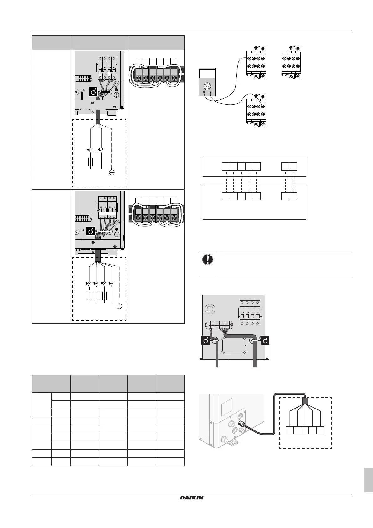
Capacity –
Power supply
F1B X14M
3kW 1N~ 230V
6kW 1N~ 230V
1N~ , 50 Hz
230 V AC
F1B.2+4
F1B.6+8
L N
Q3DI
6kW 3N~ 400V
9kW 3N~ 400V
L1 L2 NL3
3N~ , 50 Hz
400 V AC
Q3DI
F1B.6
F1B.8
L3
F1B.4
L2
F1B.2
L1 N
3 Fix the cable with cable ties to the cable tie mountings.
During connection of the backup heater, miswiring is possible. To
detect possible miswiring, it is highly recommended to measure the
resistance value of the heater elements. Depending on the capacity
and power supply, following resistance values (see table below)
should be measured. ALWAYS measure the resistance on the
contactor clamps K1M, K2M, and K5M.
3kW
1N~ 230V
6kW
1N~ 230V
6kW
3N~ 400V
9kW
3N~ 400V
K1M/1 K5M/13 52.9Ω 52.9Ω ∞ ∞
K1M/3 ∞ 105.8Ω 105.8Ω 105.8Ω
K1M/5 ∞ 158.7Ω 105.8Ω 105.8Ω
K1M/3 K1M/5 26.5Ω 52.9Ω 105.8Ω 105.8Ω
K2M/1 K5M/13 ∞ 26.5Ω ∞ ∞
K2M/3 ∞ ∞ 52.9Ω 52.9Ω
K2M/5 ∞ ∞ 52.9Ω 52.9Ω
K2M/3 K2M/5 52.9Ω 52.9Ω 52.9Ω 52.9Ω
K1M/5 K2M/1 ∞ 132.3Ω ∞ ∞
Example measure resistance between K1M/1 and K5M/13:
K1M K2MK2M
1 3 5 13
2 4 6 14
K5M
1 3 5 13
2 4 6 14
1 3 5 13
2 4 6 14
Ω
Ω
To connect the backup heater kit to the outdoor unit
The wiring between the backup heater kit and the outdoor unit is as
follows:
1 2 3 4 5
6 7 8 9 10
X3M
X15M
1 2
1 2
X5M
X15M
EKLBUHCB6W
A
B
HV LV
A Outdoor unit
B Backup heater kit
HV High voltage connections (backup heater thermal
protector + backup heater connection)
LV Low voltage connection (backup heater thermistor)
NOTICE
The distance between the high voltage and low voltage
cables should be at least 50mm.
1 On the backup heater kit, connect the LV and HV cables to the
appropriate terminals as shown in the illustration below.
2 On the outdoor unit, connect the HV cable to the appropriate
terminals as shown in the illustration below.
6 7 8 9 10
X15M
X3M.1
X3M.2
X3M.3
X3M.4
X3M.5
EKLBUHCB6W
HV