6 Electrical installation
Installation manual
22
EBLA09~16DA + EDLA09~16DA
Daikin Altherma 3 M
4P620239-1 – 2020.06
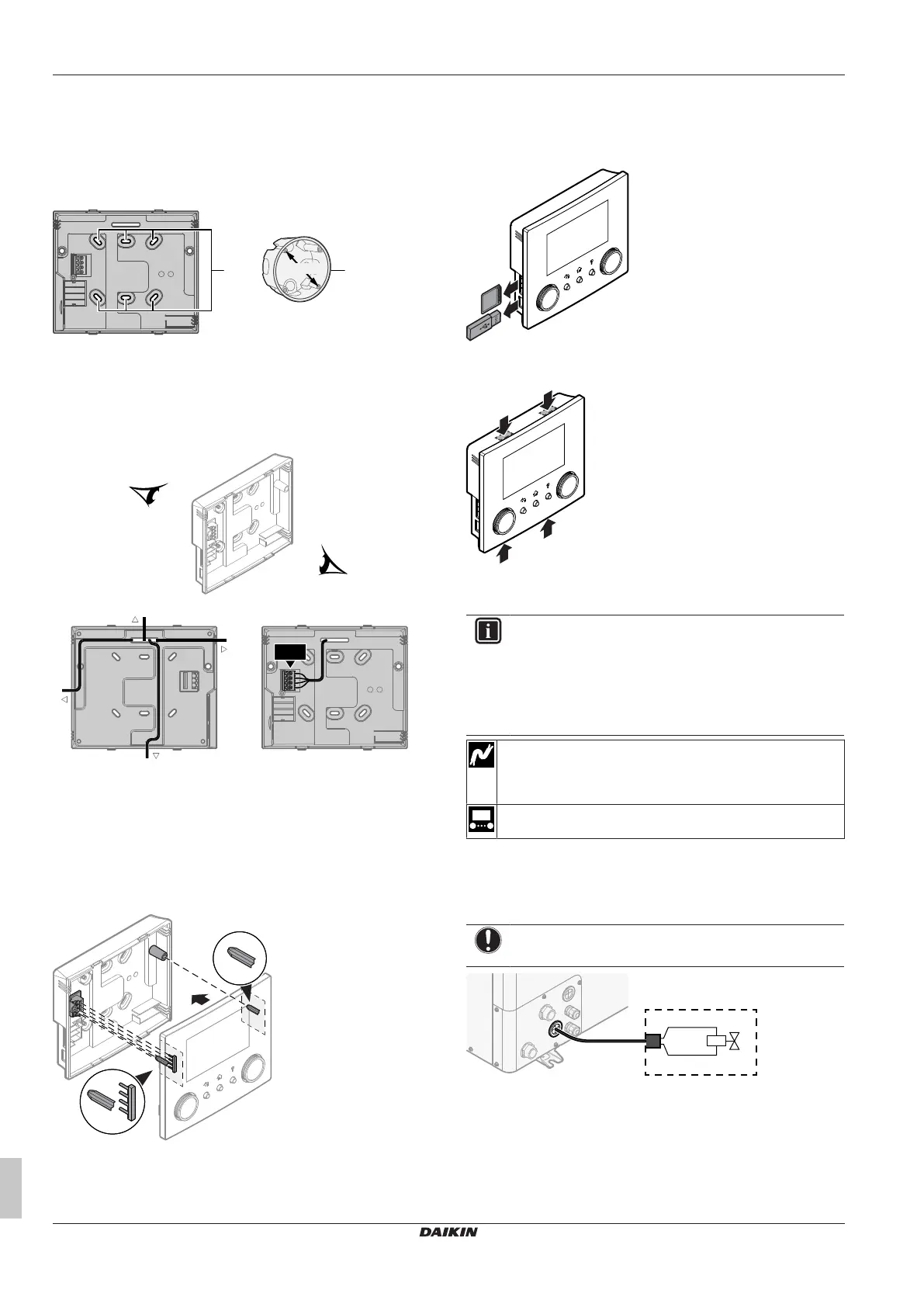
b Rear plate
c Screws
d Wall plugs
1 Mount the rear plate to the wall.
▪ Use the 2 screws and wall plugs.
▪ Use any of the 6 holes. The holes are compatible with
standard electrical box extenders of 60mm.
a Holes
b Electrical box extender (field supply)
2 Connect the user interface cable to the user interface.
▪ Choose one of the 4 possible wiring intakes (a, b, c or d).
▪ If you choose the left or right side, make a hole for the cable
in the part of the casing where the casing is thinner.
a Top side
b Left side
c Bottom side
d Right side
3 Mount the front plate.
▪ Align the positioning pins and push the front plate onto the
rear plate until it moves into place with a click.
▪ The connector pins are automatically inserted correctly.
a Positioning pins
b Connector pins
Opening the user interface after it is installed
If you need to open the user interface after it is installed, proceed as
follows:
1 Remove the WLAN cartridge and USB memory stick (if any).
2 Push the rear plate on each of the 4 spots where the snap-fits
are located.
6.3.6 To connect the shut-off valve
INFORMATION
Shut-off valve usage example. In case of one LWT zone,
and a combination of underfloor heating and heat pump
convectors, install a shut-off valve before the underfloor
heating to prevent condensation on the floor during cooling
operation. For more information, see the installer reference
guide.
Wires: 2×0.75mm²
Maximum running current: 100mA
230VAC supplied by PCB
—
1 Open the service cover. See "4.3.1 To open the outdoor
unit"[410].
2 Connect the valve control cable to the appropriate terminals as
shown in the illustration below.
NOTICE
Only connect NO (normally open) valves.