6 Electrical installation
Installation manual
21
EBLA09~16DA + EDLA09~16DA
Daikin Altherma 3 M
4P620239-1 – 2020.06
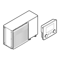
B
D
Cu
A
18°C 0.25 m
0.5 m
0.1 m
0.2 m
Alpex
A
5°C
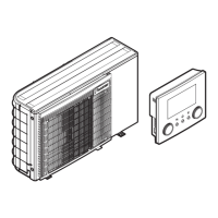
2 On the outdoor unit, connect B to the appropriate terminals as
shown in the illustration below.
3 Fix the cable with cable ties to the cable tie mountings.
6.3.5 To connect the user interface
This topic describes the following:
▪ Connecting the user interface cable to the outdoor unit.
▪ Installing the user interface, and connecting the user interface
cable to it.
▪ (if necessary) Opening the user interface after it is installed.
Connecting the user interface cable to the outdoor unit
Wires: 4×(0.75~1.25mm²)
Maximum length: 200m
[2.9] Control
[1.6] Room sensor offset
1 Open the service cover. See "4.3.1 To open the outdoor
unit"[410].
2 Connect the user interface cable to the outdoor unit. Fix the
cable with cable ties to the cable tie mountings.
X5M.11
P1P2
+
PSU
X1B
X5M.12
X5M.16
X5M.15
4
3
2
1
a User interface: Required for operation. Delivered with the
unit as accessory.
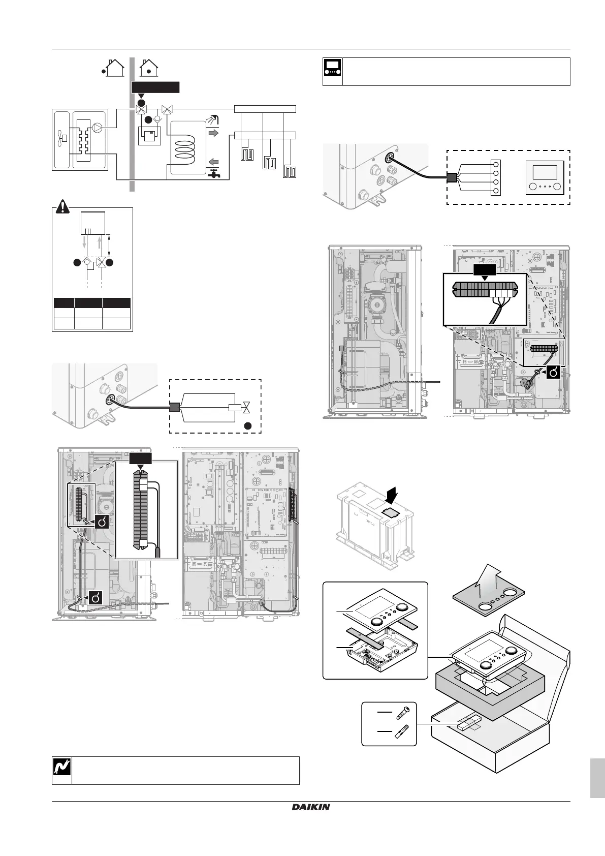
Installing the user interface, and connecting the user interface
cable to it
You need the following user interface accessories (delivered on top
of the unit):
a Front plate