6 Electrical installation
Installation manual
23
EBLA09~16DA + EDLA09~16DA
Daikin Altherma 3 M
4P620239-1 – 2020.06
3 Fix the cable with cable ties to the cable tie mountings.
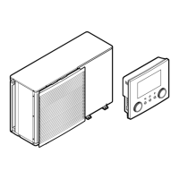
6.3.7 To connect the electricity meters
Wires: 2 (per meter)×0.75mm²
Electricity meters: 12VDC pulse detection (voltage supplied
by PCB)
[9.A] Energy metering
INFORMATION
In case of an electricity meter with transistor output, check
the polarity. The positive polarity MUST be connected to
X5M/6 and X5M/4; the negative polarity to X5M/5 and
X5M/3.
1 Open the service cover. See "4.3.1 To open the outdoor
unit"[410].
2 Connect the electricity meters cable to the appropriate terminals
as shown in the illustration below.
S2S
X5M.6
X5M.5
X5M.4
X5M.3
S3S
3 Fix the cable with cable ties to the cable tie mountings.
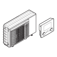
6.3.8 To connect the domestic hot water pump
Wires: (2+GND)×0.75mm²
DHW pump output. Maximum load: 2A (inrush), 230VAC,
1A (continuous)
[9.2.2] DHW pump
[9.2.3] DHW pump schedule
1 Open the service cover. See "4.3.1 To open the outdoor
unit"[410].
2 Connect the domestic hot water pump cable to the appropriate
terminals as shown in the illustration below.
3 Fix the cable with cable ties to the cable tie mountings.
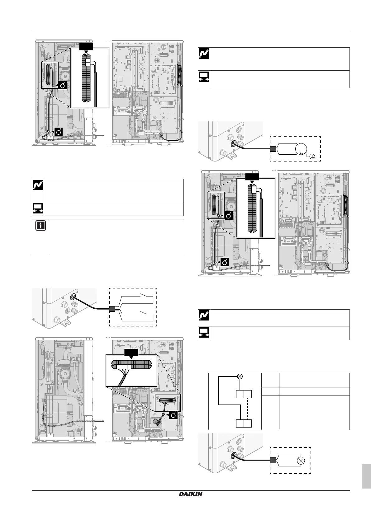
6.3.9 To connect the alarm output
Wires: (2+1)×0.75mm²
Maximum load: 0.3A, 250VAC
[9.D] Alarm output
1 Open the service cover. See "4.3.1 To open the outdoor
unit"[410].
2 Connect the alarm output cable to the appropriate terminals as
shown in the illustration below.
1+2 Wires connected to the alarm
output
3 Wire between X2M and A4P
A4P Installation of EKRP1HBAA is
required.