11 Technical data
Installation manual
44
EBLA09~16DA + EDLA09~16DA
Daikin Altherma 3 M
4P620239-1 – 2020.06
English Translation
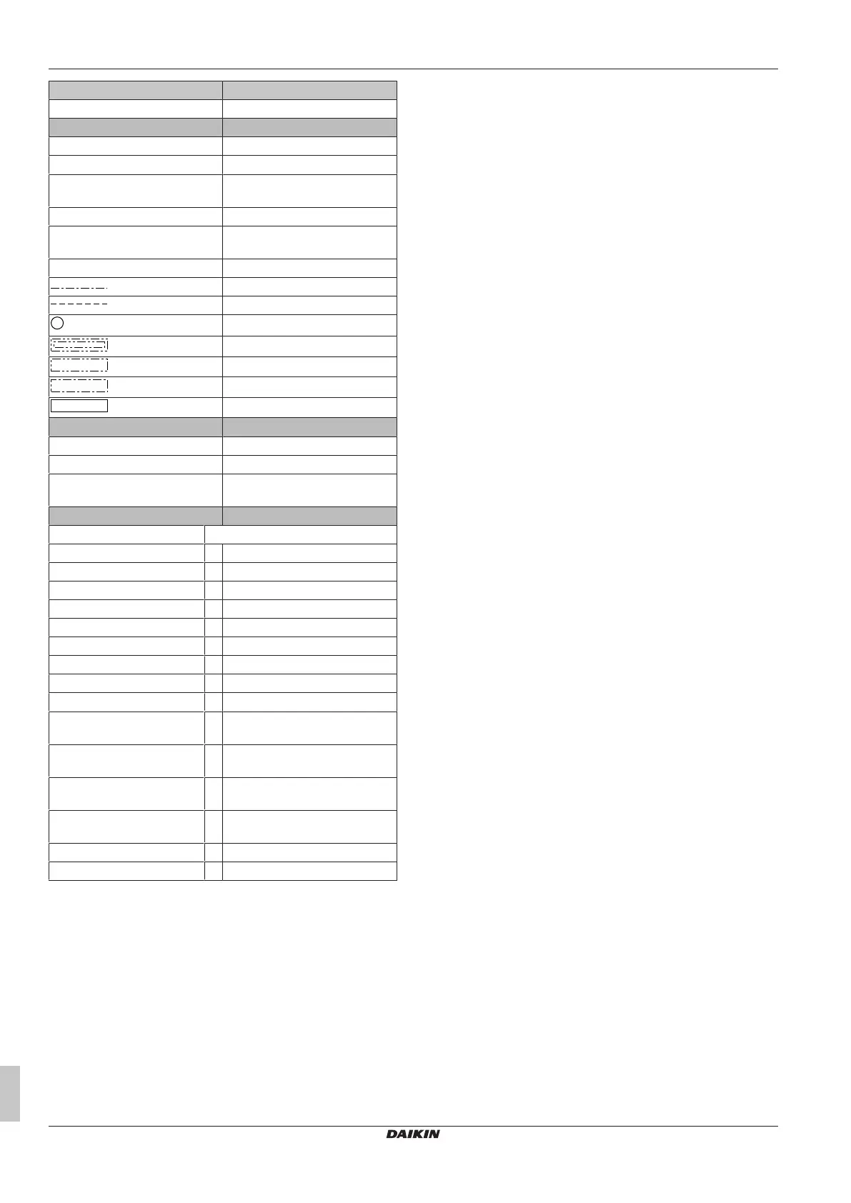
SWB2 Hydro switch box 2 (right side)
(2) Notes (2) Notes
X1M Terminal (main)
X2M Terminal (field wiring for AC)
X4M Terminal (booster heater power
supply)
X5M Terminal (field wiring for DC)
X9M Terminal (integrated backup
heater power supply)
X10M Terminal (Smart Grid)
Earth wiring
Field supply
Several wiring possibilities
Option
Wiring depending on model
Switch box
PCB
(3) BUH switch box (3) Backup heater switch box
SWB1 Hydro switch box 1 (front side)
SWB2 Hydro switch box 2 (right side)
SWB3 Hydro switch box 3 (behind
SWB2)
(4) Legend (4) Legend
*: Optional; #: Field supply
A1P Main PCB
A4P * Digital I/O PCB
A8P * Demand PCB
F1B # Overcurrent fuse backup heater
K1A, K2A * High voltage Smart Grid relay
K1M Safety contactor backup heater
K3M * Contactor booster heater
Q1DI # Earth leakage circuit breaker
TR1 Power supply transformer
X4M * Terminal strip (booster heater
power supply)
X6M # Terminal strip (power supply at
client side)
X9M Terminal strip (integrated backup
heater power supply)
X10M * Terminal (high voltage Smart
Grid)
X*A Connector
X*M Terminal strip