ON/OFF VALVE KITS
Model Name Description
EK2MV2B10C5 2 Pipes 2 Way Valve Kit
EK2MV3B10C5 2 Pipes 3 Way Valve Kit
EK4MV2B10C5 4 Pipes 2 Way Valve Kit
EK4MV3B10C5 4 Pipes 3 Way Valve Kit
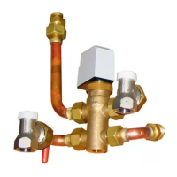
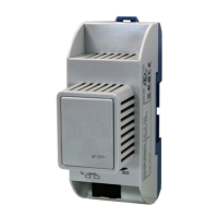
The 2-way or 3-way ON/OFF valve kits, connected to the
DAIKIN controllers, helps to set the room temperature by
interrupting the water ow to the heat exchanger. The
kits are available with various ttings for all FWE units,
both for 2-pipe and for 4-pipe systems.
The position of water input, connections to heat
exchanger and water returning to the circuit is shown in
gure 1 (2 ways type) and gure 2 (3 ways type) according
to the indications on the valve body.
The connection must be made by using “Piping Connection Diagrams” and “Pipe Description Schemas”
inside the kit box for each models. All ttings are specied in “Pipe Description Schema” with 1:1 scale to
facilitate nding the correct tting part.
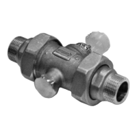
Figure for;
4 Pipe / 2 Way Valve Model Piping Connection Diagram
Figure for;
4 Pipe / 2 Way Valve Model Pipe Description Schema
Piping Connection Diagram
In these les, the letters indicate the corresponding
ttings in “pipe description schema”. The numbers
indicated the assembly sequence that has to be
followed.
Pipe Description Schema
In these les, part drawings are scaled 1:1 and the
numbers at the right of the part drawings indicate
quantity.
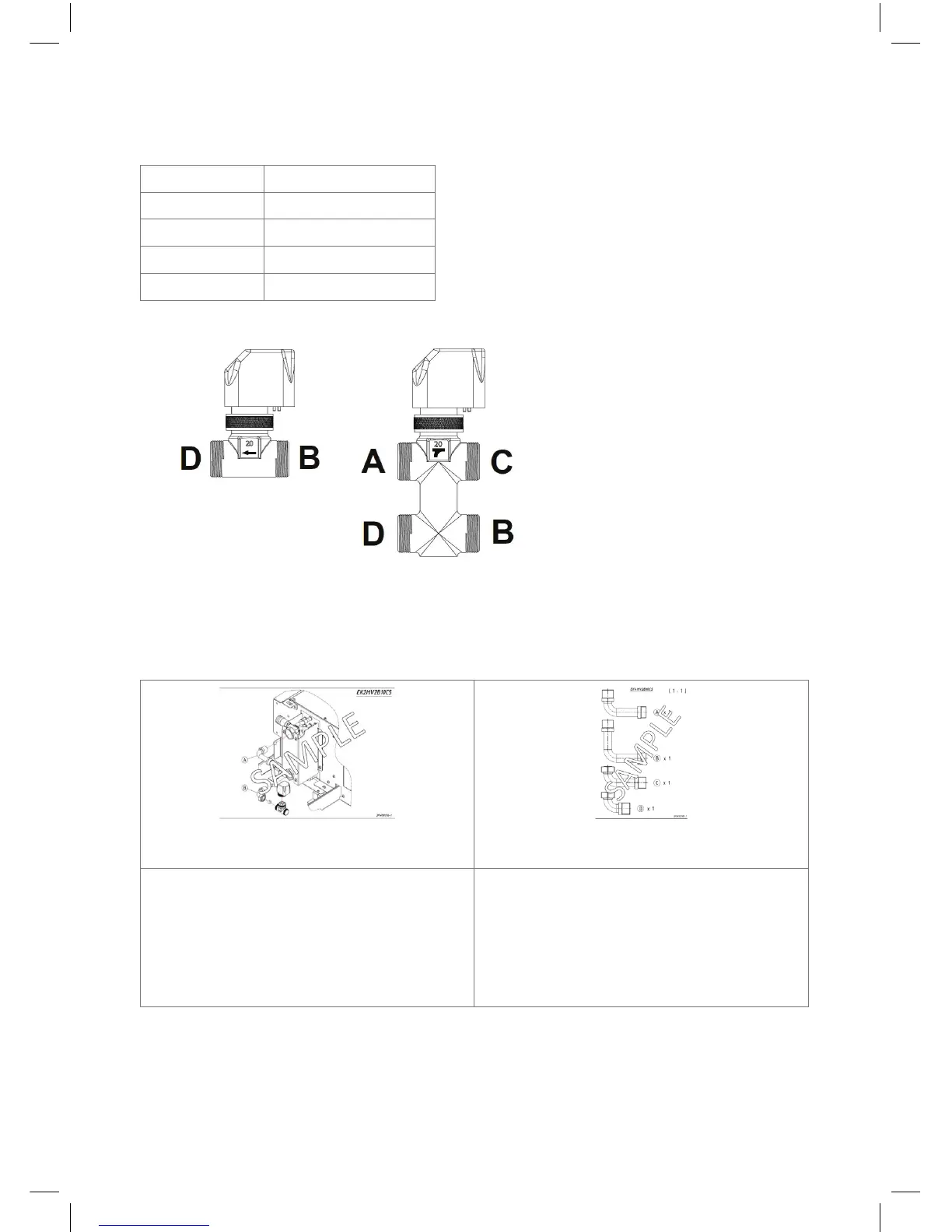
Figure 1
Figure2
A= Heat exchanger water outlet
B= Water inlet from circuit
C= Water returning to circuit
D= Heat exchanger water inlet
! WARNING:
• For electrical connection to the controller, refer to the wiring diagram of the controller.
• Each unit requires a switch (IL) on the feeder line with a distance of at least 3 mm between the opening contacts, and a suitable
safety fuse (F).
1