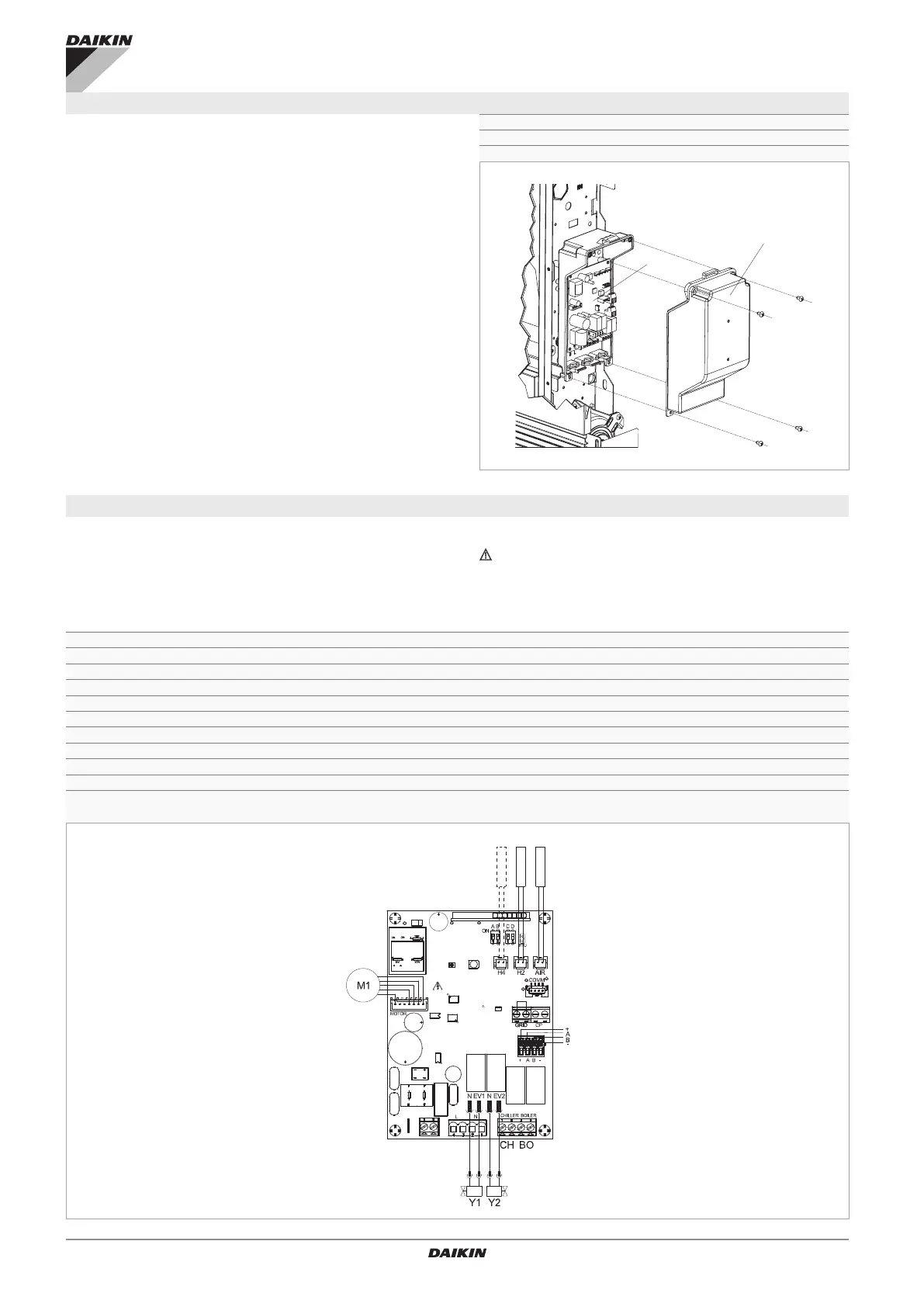
2
Access to the printed circuit board
To access the electrical connection area:
– follow the instructions in the installation manual of the
appliance
To access the Printed circuit board:
– access the electrical connection area
– unscrew the xing screws of the electric box
– remove the cover
A Cover of the electrical box
B Fixing screws
C PCB
A
C
B
B
Electrical connections EKRTCTRL1
For connection of the electronic board to a "Modicon Mod-
Bus" RTU serial communication network:
– follow the indication on the connection diagram
– collegarsi al connettore ModBus con serigraa presente
sulla scheda
– connect respecting the indication "A" and "B"
For all other connections, refer to the diagrams and in-
structions in the installation manual.
+BA- ModBus RTU serial connection
H2 Hot water temperature probe 10 kΩ
AIR Optional air probe
M1 Fan motor DC Inverter
S1 Grid safety microswitch
CP Presence input sensor
Y1 (N-EV1) Water solenoid valve (230 V/50 Hz 1 A power output)
L-N 230 V/50 Hz electrical power supply connection
BO Boiler consent output (free contact max 1 A)
CH Chiller consent output (free contact max 1 A)
N540022B