1
INSTALLATION, CONNECTION AND SETTINGS WALL MOUNTED
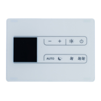
CONTROL EKWHCTRL1, EKRTCTRL1 FOR USE IN A MODBUS RTU
SERIAL NETWORK
Warnings
This instruction manual forms an integral part of the de-
vice and therefore must be carefully preserved and must
ALWAYS travel with it, even if you transfer the device to
another owner or relocate it to other premises.
If the manual gets damaged or lost, download a copy
from the website.
For a rapid and right assembly of the components follow
carefully the sequences described in the various sections.
All the operations must be performed by qualied person-
nel using the required Personal Protective Equipment.
This document is restricted in use to the terms of the law
and may not be copied or transferred to third parties with-
out the express authorization of the manufacturer.
Description
The terminal board +AB- of the INN-FR-B32 Printed circuit
board allows the connection of the same present in the con-
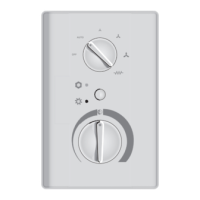
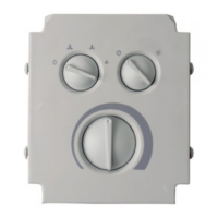
trol panels EKRTCTRL1, EKWHCTRL1 and EKWHCTRL0 to a se-
rial communication network "Modicon ModBus" RTU.
The EKWHCTRL0 kit can only be installed in combination
with the electronic controls EKWHCTRL1. In this case the
connection from the electronic board INN-FR_B32 is not
necessary because the electronic controls EKWHCTRL1
have a specic serial port to connect.
A INN-FR-B32 board
Electric connections
Preliminary warnings
Before each intervention:
• disconnect the device from the power mains by turning
the system master switch to "OFF"
• wait for the components to cool down in order to avoid
any burns
Make sure that there is no voltage before operating.
Any technical intervention before disconnecting the unit
from the power supply is forbidden.


