Installation manual
1
4PW17562-1A
EPIMSA6 + EPIB6
Master/Slave interface + Power interface
The Master/Slave interface or Power interface must
be installed to use microprocessor-based control panels
on the whole range of units for models with a current
consumption greater than 5 A.
The EPIMSA6 Master/Slave interface is used for
connecting up to 4 units in parallel to 1 controller
FWEC(1,2,3)A. Up to 3 EPIMSA6 interfaces can be
connected in parallel to 1 controller. The capacity of the
EPIMSA6 contacts is 4 x 3 A.
The EPIB6 Power interface permits to use the electronic
remote controller FWEC(1,2,3)A on the whole range of
units with a current consumption greater than 5 A. The
capacity of the EPIB6 contacts is 16 A.
Neglecting the absolute requirement to install
an additional interface (EPIB6 or EPIMSA6) to
units with a current consumption greater than
5 A may cause re or other damage to the
equipment.
Table below lists the maximum current of the whole
range of units.
FWL/FWM/FWV FWB FWD
01 0.16 A - -
02 0.21 A 0.56 A -
03 0.27 A 0.56 A -
04 0.39 A 0.56 A 0.95 A
05 - 1.10 A -
06 0.38 A 1.10 A 1.58 A
07 - 1.10 A -
08 0.80 A 1.40 A 1.97 A
09 - 1.40 A -
10 1.12 A 1.40 A 1.97 A
12 - -
3.21 A
16 - -
5.37 A
18 - -
5.37 A
<=3 A
Master/Slave function is possible by installing the EPIMSA6.
>3 A
Installing EPIMSA6 you must install EPIB6.
>5 A
EPIB6 must be installed.
TEchNical SpEcificaTiONS
EPIMSA6 EPIB6
Power supply
230 V
–15% +10% 50 Hz
Contacts at output 4x3A 250 V 1x16A 250 V
Operating temperature 0~40°C
Humidity limits (RH) 20~80% non-condensing
Protection rating IP30
Container 105 x 90 x 70 mm
Weight 265 g
iNSTallaTiON
n All eld wiring and components must be
installed by a licensed electrician and must
comply with relevant local and national
regulations.
n Before obtaining access to terminals, all
power supply circuits must be interrupted.
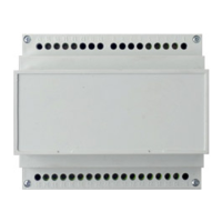
n The EPIMSA6 or EPIB6 interfaces are to be installed
on a DIN guide, usually housed in the electric boards
cabinet.
n The overall dimensions of the EPIMSA6 and EPIB6
interface are shown in gure 3.
n Make the electrical connections with POWER OFF as
indicated in the diagrams of gure 1+2 that show the
following:
Figure 1: microprocessor-based controller + 2x
EPIMSA6 connected to 8 units.
Figure 2: connections of EPIB6
Each unit requires a switch (IL) on the power supply line
with a distance of at least 3 mm between the opening
contacts, and a suitable safety fuse (F).
NOTE
Connect only one unit per EPIMSA6 or
EPIB6 output.
EPIMSA6
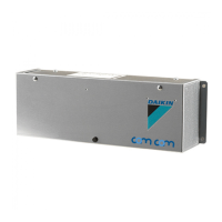
EPIB6
Master/Slave interface
Power interface
Installation manual
 Loading...