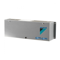
The Daikin EKFCMBCB7 Modbus interface PCB kit is an optional accessory designed to enable Modbus RTU (RS485) communication for FWF (Fan Coil Unit Wall Mounted) or FWC (Fan Coil Unit Cassette) fan coil units. This kit allows the fan coil unit to integrate into a centralized control system using the Modbus protocol, providing enhanced control and monitoring capabilities.
Function Description:
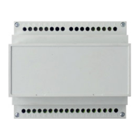
The primary function of the EKFCMBCB7 kit is to convert the fan coil unit's native communication protocol to Modbus RTU (RS485). This allows the fan coil unit to be controlled and monitored by a Modbus master device, such as a Building Management System (BMS) or a central controller. The kit includes the Modbus interface PCB, various wires for power supply and communication, tie wraps, spacers, and an installation manual.
The Modbus interface PCB acts as a gateway, translating commands from the Modbus master to the fan coil unit and relaying status information from the fan coil unit back to the Modbus master. This enables functionalities such as setting operating modes, fan speeds, temperature setpoints, and reading operational status, alarms, and sensor data.
Important Technical Specifications:
- Communication Protocol: Modbus RTU (RS485)
- Compatibility: FWF and FWC fan coil units
- Communication Wires:
- Wire Type: Twisted pair sheathed cable
- Wire Size: 0.75~1.25 mm²
- Maximum Total Wire Length: 500 m
- Modbus Address Setting: The Modbus address is derived from the group number set on the wired remote controller. Group numbers (remote controller addresses) from 1-00 to 4-15 correspond to Modbus addresses from 1 to 64. For example, 1-00 corresponds to Modbus address 1, 1-01 to Modbus address 2, 1-15 to Modbus address 16, 2-15 to Modbus address 32, and 4-15 to Modbus address 64.
- Maximum Connections:
- Maximum 16 remote controller addresses can be connected to a Modbus PCB.
- Maximum 64 remote controller addresses can be used on a central remote controller.
- Maximum 8 Modbus PCBs can be connected on a 0.75 mm² wire.
- Maximum 15 FWF or FWC units can be connected on a FWF or FWC unit which has its own remote controller address.
- Termination: The cable terminal (resistor) is integrated into the Modbus PCB and is enabled via DIP switch SS2. If the Modbus PCB is used as a cable terminal at the end of the Modbus communication line, SS2 must be set to ON; otherwise, it must be set to OFF. DIP switch SS1 must always be set to OFF.
Usage Features:
- Installation: The kit requires careful installation by a licensed electrician in compliance with local and national regulations. The installation method varies depending on the fan coil unit model (FWF or FWC) and requires specific installation boxes (KRP1BA101 for FWF models, KRP1H98 for FWC models). The PCB is mounted within these boxes, and connections are made to the fan coil unit's PCB for power and communication, as well as to the field communication wiring.
- Remote Controller Integration: The Modbus PCB integrates with the fan coil unit's wired remote controller. The group number set on the wired remote controller directly translates to the Modbus address, simplifying address configuration.
- Flexible Network Configuration: The system supports various external connection possibilities, allowing for centralized control of multiple fan coil units. Units can be configured to have their own remote controller address or share an address, depending on the control requirements. The Modbus communication line can be terminated at the last Modbus PCB in the chain using the SS2 DIP switch.
- Error Indication: The PCB features LED indicators for operational status and error diagnosis:
- HAP (Green):
- ON: CPU error
- Blinking: Normal CPU operation
- H5P (Orange):
- ON: Normal Modbus communication
- Blinking: Modbus communication error
- H6P (Orange):
- ON: Normal fan coil unit communication
- Blinking: Fan coil unit communication error
Maintenance Features:
- Diagnostic LEDs: The LED indicators (HAP, H5P, H6P) provide immediate visual feedback on the status of the CPU, Modbus communication, and fan coil unit communication. This helps in quickly identifying and troubleshooting issues, reducing downtime.
- Clear Installation Manual: The kit comes with a detailed installation manual (4PW65443-1B) that provides step-by-step instructions for installation, wiring, and configuration. This ensures proper setup and facilitates future maintenance or modifications.
- Professional Installation Requirement: The manual emphasizes that installation and attachment of equipment or accessories must be performed by a professional to prevent electric shock, short-circuits, leaks, fire, or other damage. This ensures the safety and longevity of the system.
- Daikin Dealer Support: For Modbus integration and system-specific information, users are advised to contact their Daikin dealer, ensuring access to expert support and system-specific knowledge.
- Safety Precautions: The manual highlights critical safety warnings, including switching off all power before working on electrical parts and avoiding bending the PCB when connecting or removing connectors. These precautions are essential for safe operation and maintenance.
- Cable Management: Instructions to avoid squeezing bundled cables and to ensure cables do not contact sharp edges contribute to the long-term reliability and safety of the wiring.