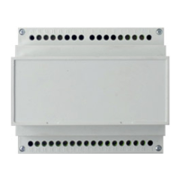
EPIMSA6 + EPIB6
Master/Slave interface + Power interface
4PW17562-1A
Installation manual
2
WiriNg parTS TablE
Figure 1: connections of EPIMSA6
BK ................ Black (maximum speed)
BN................ Brown
BU................ Blue (medium speed)
EPIMSA6 ..... Master/Slave interface
F .................. Fuse (eld supply)
GN ............... Green
GY ............... Grey
IL.................. Line switch (eld supply)
M .................. Fan motor
RD ............... Red (minimum speed)
VC................ Cold water valve
VH................ Hot water valve
WH ............... White (Common)
YE ................ Yellow
3/7................ 3 out of 7 speeds
----- ............... Electrical connections
to be made by the installer.
Figure 2: connections of EPIB6
A - Power supply 230 V 1~50 Hz
14+15 .......... phase
16+17 .......... neutral
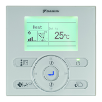
B - Connection line to control panel
1................... fan motor common wire
2................... minimum motor speed
3................... medium motor speed
4................... maximum motor speed
C - Connection line to motor
28................. fan motor common wire
27................. maximum motor speed
26................. medium motor speed
25................. minimum motor speed
NOTES