ERHQ006~008BBV3 + ERLQ006~008BBV3
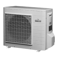
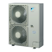
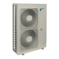
Outdoor unit for air to water heat pump
4PW68002-1A – 03.2011
Installation manual
5
3.6. Handling
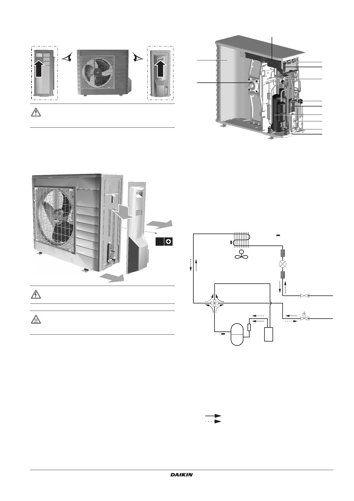
As shown in the figure below, slowly move the unit by grabbing the
left and right grips.
4. OVERVIEW OF UNIT
4.1. Opening the unit
4.2. Main components
1 Heat exchanger
2 Fan motor
3 Switch box with main pcb (inverter and control pcb)
4 Terminal communication and power supply
5 Service pcb
6 4-way valve
7 Electronic expansion valve (main)
8 Accumulator
9 Compressor
10 Liquid stop valve
11 Gas stop valve
12 Service port
4.3. Functional diagram
1 Thermistor (air)
2 Heat exchanger
3 Thermistor (heat exchanger)
4 Fan motor
5 Filter
6 Electronic expansion valve
7 Liquid stop valve
8 Gas stop valve with service port
9 Accumulator
10 Compressor
11 Thermistor (discharge)
12 4-way valve (ON=heating)
Cooling
Heating
CAUTION
To avoid injury, do not touch the air inlet or aluminium fins
of the unit.
DANGER: ELECTRICAL SHOCK
See "2. General safety precautions" on page 2.
DANGER: DO NOT TOUCH PIPING AND INTERNAL
PARTS
See "2. General safety precautions" on page 2.
A B
A
B
1
1x
3
2
1
4
5
6
7
10
9
11
12
8
3
2
M
8
9
1011
12
7
5
5
1
2
3
4
6



 To Next Page