Do you have a question about the Daikin ERQ200A7W1B and is the answer not in the manual?
Provides essential safety guidelines and warnings for handling the equipment.
Details specific safety precautions to be observed during repair work.
Outlines important safety considerations and warnings after repair completion.
Describes necessary checks to perform after repair work is completed.
Identifies model names for outdoor units, control boxes, and expansion valve kits.
Explains the different types and functions of control boxes used in the system.
Describes the expansion valve kits and their specifications for system connection.
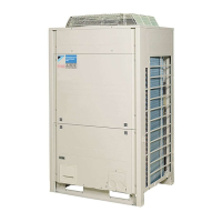
Details the technical specifications for the outdoor units.
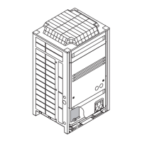
Illustrates the layout of functional parts within the system.
Shows the functional parts layout for the ERQ 125 A7W1B outdoor unit.
Shows the functional parts layout for the ERQ 200 A7W1B outdoor unit.
Shows the functional parts layout for the ERQ 250 A7W1B outdoor unit.
Explains the fundamental control logic and operations of the system.
Explains the Proportional-Integral control for compressor capacity adjustment.
Details specific operational modes and controls like startup and oil return.
Details procedures for controlling compressor startup and pressure equalization.
Explains the operation to recover oil from the compressor back into the system.
Describes oil return operation specifically for heating mode.
Details the process for defrosting the outdoor unit heat exchanger to maintain capacity.
Covers safety mechanisms and protection controls against malfunctions.
Details the control mechanisms to prevent damage from high pressure.
Explains the protection controls against transient decreases in low pressure.
Describes protection against high discharge pipe temperatures.
Covers protection mechanisms related to inverter overcurrent and fin temperature.
Explains overload protection for standard compressors.
Details the injection control for compressor protection on a specific model.
Describes emergency operation mode for a specific outdoor unit model.
Details the system's freeze prevention operation for the AHU heat exchanger.
Explains protection measures against low outdoor air temperatures.
Provides wiring diagrams for the control boxes.
Provides the wiring diagram for the D-box control unit.
Presents the wiring diagram for the F-box control unit.
Outlines crucial steps and checks required before starting the installation.
| Category | Heat Pump |
|---|---|
| Model | ERQ200A7W1B |
| Cooling Capacity | 20.0 kW |
| Heating Capacity | 22.4 kW |
| Refrigerant | R-32 |
| Power Supply | 400V, 3-phase, 50Hz |