6 Electrical installation
Installation manual
18
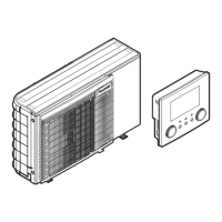
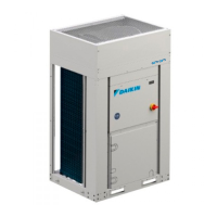
EWAA004~008D + EWYA004~008D
Packaged air-cooled water chillers
and packaged air to water heat pumps
4P688014-1D – 2022.10
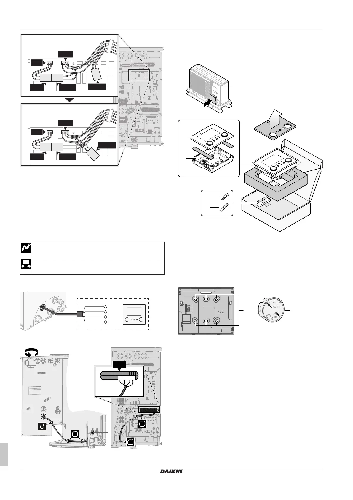
X19A
X1A
X11Y X11YA
X11YA
X11YB
X19A
X1A
X11Y X11YB
5 Fix the cables with cable ties to the cable tie mountings.
6.3.3 To connect the user interface
This topic describes the following:
▪ Connecting the user interface cable to the outdoor unit.
▪ Installing the user interface, and connecting the user interface
cable to it.
▪ (if necessary) Opening the user interface after it is installed.
Connecting the user interface cable to the outdoor unit
Wires: 4×(0.75~1.25mm²)
Maximum length: 200m
[2.9] Control
[1.6] Room sensor offset
1 Connect the user interface cable to the outdoor unit. Fix the
cable with cable ties to the cable tie mountings.
X1B
a
X5M.11
X5M.12
X5M.16
X5M.15
1
2
3
4
P1P2
+
PSU
a User interface: Required for operation. Delivered with the
unit as accessory.
Installing the user interface, and connecting the user interface
cable to it
You need the following user interface accessories (delivered on top
of the unit):
a Front plate
b Rear plate
c Screws
d Wall plugs
1 Mount the rear plate to the wall.
▪ Use the 2 screws and wall plugs.
▪ Use any of the 6 holes. The holes are compatible with
standard electrical box extenders of 60mm.
a Holes
b Electrical box extender (field supply)
2 Connect the user interface cable to the user interface.
▪ Choose one of the 4 possible wiring intakes (a, b, c or d).
▪ If you choose the left or right side, make a hole for the cable
in the part of the casing where the casing is thinner.
 Loading...