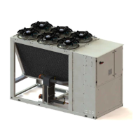
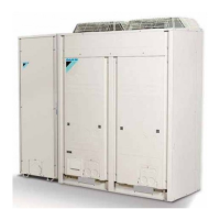
ESIE10-01 General Outline
Part 1 – System Outline 1–11
3
1
4
5
Control section - main features
Q Management of the compressor stepless capacity and fans modulation.
Q Chillers enabled to work in partial failure condition.
Q Full routine operation at condition of:
• high ambient temperature value.
• high thermal load.
• high evaporator entering water temperature (start-up).
Q Display of evaporator entering/leaving water temperature.
Q Display of Outdoor Ambient Temperature.
Q Display of condensing-evaporating temperature and pressure, suction and discharge superheat for
each circuit.
Q Leaving water evaporator temperature regulation. Temperature tolerance = 0.1°C.
Q Compressors and evaporator pumps hours counter.
Q Display of Status Safety Devices.
Q Number of starts and compressors working hours.
Q Optimized management of compressors load.
Q Fan management according to condensing pressure.
Q Re-start in case of power failure (automatic / manual).
Q Soft Load (optimized management of the compressors load during the start-up).
Q Start at high evaporator water temperature.
Q Return Reset (Set Point Reset based on return water temperature).
Q OAT (Outside Ambient temperature) Reset.
Q Set point Reset (optional).
Q Application and system upgrade with commercial SD cards.
Q Ethernet port for remote or local servicing using standard web browsers.
Q Two different sets of default parameters could be stored for easy restore.
Safety device / logic for each refrigerant circuit
Q High pressure (pressure switch).
Q High pressure (transducer).
Q Low pressure (transducer).
Q Fans circuit breaker.
Q High compressor discharge temperature.
Q High motor winding temperature.
Q Phase Monitor.
Q Low pressure ratio.
Q High oil pressure drop.
Q Low oil pressure.
Q No pressure change at start.
System security
Q Phase monitor.
Q Low Ambient temperature lock-out.
Q Freeze protection.

 Loading...
