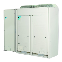
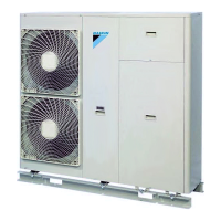
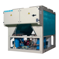
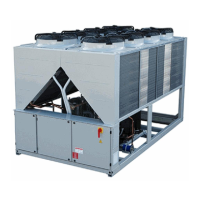
EWAQ016~064BAW + EWYQ016~064BAW
Packaged air-cooled water chiller
4PW70082-1C – 2013.07
Installation and operation manual
8
4.4. Overview of the unit
4.4.1. Main components of the outdoor module
Functional diagram of the outdoor module
1 Electronic expansion valve (subcooling) (Y2E)
2 Electronic expansion valve (main) (Y1E)
3 Check valve
4 Filter
5 Fan
6 Fan motor (M1F,M2F)
7 Heat exchanger
8 Distributor
9 Pressure regulating valve
10 Refrigerant regulator
11 4-way valve (heat exchanger)(Y3S)
12 Solenoid valve (Y1S)
13 High pressure sensor (SENPH)
14 Solenoid valve (Y2S)
15 Oil separator
16 High pressure switch
17 Capillary tube
18 Compressor (INV)
19 Compressor (STD1)
20 Compressor (STD2)
21 Low pressure sensor (SENPL)
22 Service port (refrigerant charge)
23 Stop valve (liquid pipe)
24 Stop valve (gas pipe)
25 Electrical component box
4.4.2. Main components of the hydro module
Hydraulic compartment (panel 3)
1. Air purge valve
Remaining air in the water circuit will be automatically removed
via the air purge valve. (Refer to "[E-04] Pump only operation (air
purge function)" on page 21.)
2. Temperature sensors
Temperature sensors determine the water and refrigerant
temperature at various points in the water and refrigerant circuit.
3. Heat exchanger
4. Expansion vessel: 12 l
5. Refrigerant liquid connection
6. Refrigerant gas connection
7. Shut-off valves (field installed)
The shut-off valves on the water inlet connection and water
outlet connection allow isolation of the unit water circuit side
from the residential water circuit side. This facilitates draining
and filter replacement of the unit.
16
7
10
16
16
5
6
5
25
20
19
6
1
2
11
12
18
23
24
14
22
M
INV
SV
HPS
STD1
HPS
STD2
HPS
SENPH
SENPL
SV
1 3
4
17
5 842 69 7
4
22
13
10
4 4 4 4
15 15 15
3
18 20
21
23
3
12
11
3
14 16 16 16444
17
17
24
19
17
13
3
1
4
7+9
7+8
14
6
2
18
17
5
2
12
15
11
10
16
4PWEN70082-1C.book Page 8 Wednesday, September 25, 2013 7:31 AM
 Loading...