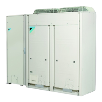
EWAQ016~064BAW + EWYQ016~064BAW
Packaged air-cooled water chiller
4PW70082-1C – 2013.07
Installation and operation manual
12
4.5.6. Fill the water circuit
1 Connect the water supply to the drain and fill valve (see
"4.4.2. Main components of the hydro module" on page 8).
2 Make sure the automatic air purge valve is open (at least
2 turns).
3 Fill with water until the pressure gauge indicates a pressure of
approximately 2.0 bar. Remove air in the circuit as much as
possible using the air purge valves (refer to "[E-04] Pump only
operation (air purge function)" on page 21.
4.6. Connect the electrical wiring
4.6.1. Internal wiring – Parts table – Outdoor module
Refer to the wiring diagram sticker on the outdoor module. The
abbreviations used are listed below:
A1P~A8P............... Printed circuit board (main, sub 1, sub 2, noise
filter, inverter, fan, current sensor)
BS1~BS5............... Push button switch (mode, set, return, test,
reset)
C1,C63,C66........... Capacitor
E1HC,E2HC .......... Crankcase heater
F1U........................ Fuse (DC 650 V, 8 A)
F1U........................ Fuse (T, 3.15 A, 250 V)
F1U,F2U ................ Fuse (T, 3.15 A, 250 V)
F5U........................ Field fuse (field supply)
F400U.................... Fuse (T, 6.3 A, 250 V)
H1P~H8P .............. Pilot lamp
H2P........................ Under preparation or in test operation when
blinking
H2P........................ Malfunction detection when light up
HAP ....................... Pilot lamp (service monitor - green)
K1,K3..................... Magnetic relay
K1R........................ Magnetic relay (K2M, Y4S)
K2,K4..................... Magnetic contactor (M1C)
K2R........................ Magnetic relay (Y5S)
K3R........................ Magnetic relay (Y1S)
K4R........................ Magnetic relay (Y8S)
K5R........................ Magnetic relay (Y2S)
K5R........................ Magnetic relay (for option)
K6R........................ Magnetic relay (Y7S)
K7R,K8R................Magnetic relay (E1HC, E2HC)
K11R......................Magnetic relay (Y3S)
L1R ........................Reactor
M1C,M2C...............Motor (compressor)
M1F,M2F ................Motor (fan)
PS ..........................Switching power supply
Q1DI.......................Earth leakage protector (field supply)
Q1RP .....................Phase reversal detection circuit
R1T ........................Thermistor (air, fin)
R2T~R15T .............Thermistor
(H/E gas 1, H/E de-icer 1, sub cool H/E gas 1,
sub cool H/E liquid, H/E liquid 1, suction 1,
liquid 1, suction 2, H/E gas 2, H/E de-icer 2, sub
cool H/E gas 2, liquid 2, H/E liquid 2)
R10 ........................Resistor (current sensor)
R31T,R32T.............Thermistor (discharge) (M1C,M2C)
R50,R59.................Resistor
R90 ........................Resistor (current sensor)
R95 ........................Resistor (current limiting)
S1NPH...................Pressure sensor (high)
S1NPL....................Pressure sensor (low)
S1PH~S3PH ..........Pressure switch (high)
SD1........................Safety devices input
T1A ........................Current sensor
V1R........................Diode bridge
V1R,V2R................Power module
X1A~X9A ...............Connector
X1M........................Terminal strip (power supply)
X1M........................Terminal strip (control)
Y1E~Y5E ...............Electronic expansion valve
(main 1, sub cool 1, main 2, charge, sub cool 2)
Y1S~Y10S .............Solenoid valve
(RMTG, 4 way valve–H/E gas 1, RMTL, hot gas,
EV bypass 1, RMTT, RMTO, 4 way valve–H/E
gas 2, EV bypass 2)
Z1C~Z10C .............Noise filter (ferrite core)
Z1F.........................Noise filter (with surge absorber)
L1,L2,L3.................Live
N ............................Neutral
...............Field wiring
..................Terminal strip
..........................Connector
..........................Terminal
..........................Protective earth (screw)
BLK ........................Black
BLU........................Blue
BRN .......................Brown
GRN.......................Green
GRY .......................Grey
ORG.......................Orange
PNK........................Pink
RED .......................Red
WHT.......................White
YLW .......................Yellow
INFORMATION
■ During filling, it might not be possible to remove all air
in the system. Remaining air will be removed through
the automatic air purge valves during first operating
hours of the system. Additional filling with water
afterwards might be required.
■ The water pressure indicated on the pressure gauge
will vary depending on the water temperature (higher
pressure at higher water temperature).
However, at all times water pressure should remain
above 1 bar to avoid air entering the circuit.
■ The unit might dispose some excessive water through
the pressure relief valve.
■ Water quality must be according to EU directive
98/83 EC.
NOTICE
If no glycol is in the system in case of a power supply
failure or pump operating failure, drain the system. When
water is at standstill inside the system, freezing is very
likely to happen and damaging the system in the process.
WARNING
Switch off the power supply before making any
connections.
INFORMATION
The wiring diagram on the outdoor module is only for the
outdoor module.
For the hydro module or optional electrical components,
refer to the wiring diagram of the hydro module.
4PWEN70082-1C.book Page 12 Wednesday, September 25, 2013 7:31 AM
 Loading...