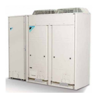
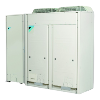
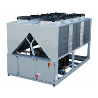
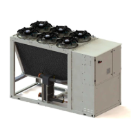
EWAQ080~260DAYN
Packaged air-cooled water chillers
4PW35556-1E
Operation manual
18
Tasks of the info menu
Consulting additional unit information
1 Enter the
INFO MENU
through the main menu. (Refer to the
chapter "How to enter a menu" on page 8).
The controller enters the
TIME INFO
screen which contains the
following information: the
TIME
and
DATE
.
2 Press Ì to consult the first
UNIT INFO
screen.
This screen contains information about the unit name, number of
circuits, evaporators and coils, EEV and the refrigerant used.
3 Press Ì to consult the second
UNIT INFO
screen.
This screen contains information about the fans, volt/ampere
and if there is a second pump or heater tape applied.
4 Press Ì to consult the
SW INFO
(software information) screen.
This screen contains information about the PCB software
versions.
Tasks of the input/output menu
Checking the status of the inputs and outputs
The input/output menu provides a means of checking the status of
the digital inputs and the status of the relay outputs.
The locked digital inputs are:
■
EMERGENCY STOP
: whether the emergency button has been
pressed (only effective if there is an emergency stop present).
■
FLOWSWITCH
: indicates the status of the flowswitch (flow/no
flow).
■
HEATER TAPE
: indicates if the heater tape is activated or not.
■
PUMPINTERLOCK
: indicates if the status of the pump interlock
is open or closed.
■
PUMP
: indicates if the pump is on or off.
■
C1
/
2 REV.PH.PROT.
: (reverse phase protector) indicates the
actual status of this safety of circuit 1/2.
■
C1
/
2 HIGH PR.SW.
: (high pressure switch) indicates the
actual status of this safety of circuit 1/2.
■
INT.L C11
/
C12
/
C21
/
22
: (interlock to compressor) indicates
the actual status of this safety of circuit1/2.
■
C1
/
2 FANOVERC.
ST.
1
/
2
/
3
: (fan overcurrent status
step 1/2/3) indicates the actual status of this safety of circuit 1/2.
The locked relay outputs are:
■
C11
/
12
/
21
/
22
: indicates whether the circuit 1/2 is on or off.
■
C1
/
2 FANSTEP 1
/
2
/
3
: indicates if the fans of fanstep 1/2/3 for
the circuit 1/2 are on or not.
Checking the status of the digital changeable inputs and
outputs
The possible settings for the changeable digital inputs are:
■
NONE
: indicates there is no function selected for this input
■
STATUS
: indicates the position of the connected switch.
■
DUAL SETPOINT
: indicates the position of the remote dual
setpoint switch: setpoint 1 or setpoint 2.
■
REMOTE ON/OFF
: indicates the position of the remote on/off
switch.
■
CAP LIMIT 25%
/
50%
/
75%
/
SET
: indicates the position of the
"enable/disable capacity limitation" switches.
■
LOW NOISE
: indicates the status of the low noise mode.
■
FREE COOLING REQ
: indicates if the free cooling is requested
or not requested.
■
FAN FORCED ON
: indicates if the fan forced on is activated or
not activated.
The possible settings for the changeable relay outputs are:
■
NONE (OPEN)
: Digital output open.
■
CLOSED
: Digital output closed.
■
2ND PUMP
: indicates the status of the second pump.
■
100% CAPACITY
: indicates when the unit is working at 100%.
■
FULL CAPACITY
: indicates when the unit is working at
maximum capacity, example reached 100% capacity or reached
maximum capacity because of safety limitation.
■
FREE COOLING
: indicates the status of the 3-way water valve
when the unit is in free cooling state.
■
GEN.OPERATION
: indicates when the unit is active.
■
SAFETY+W (NO)
: indicates when safety or warning is active
(Normal Open contact).
■
SAFETY+W (NC)
: indicates when safety or warning is active
(Normal Closed contact).
■
SAFETY (NO)
: indicates when safety is active (Normal Open
contact).
■
SAFETY (NC)
: indicates when safety is active (Normal Closed
contact).
■
C1
/
2 SAFETY
: indicates when circuit 1/2 safety is active.
■
WARNING
: indicates when warning is active.
■
C1
/
2 OPERATION
: indicates when circuit 1/2 operation is
active.
Checking the status of the analogue changeable inputs and
output
The possible settings for the analogue changeable inputs and output
are:
■
NONE
: no function is appointed to the changeable analogue
input.
■
STATUS
: only displays the status by means of test
■
FLOATING SETP
: floating setpoint based on ambient or
analogue input
■
TEMPERATURE
: only displays the (by example) condenser
outlet temperature
■
DI***
: refer to the possible functions for changeable digital
inputs. (*** can be any of the following:
STATUS
,
DUAL
SETPOINT
,
REMOTE ON/OFF,
CAP. LIMIT
,
LOW NOISE
,
FREE COOLING REQ
or
FAN FORCED ON
.)
Checking the communication inputs and outputs (option
EKACPG)
The communication inputs and outputs are:
■
RS232 ONLINE
: indicates if the RS232 communication line is
active.
■
RS485 ONLINE
: indicates if the RS485 communication line is
active.
■
DIII ONLINE
: indicates if the DIII communication line is
active.
To check the inputs and outputs, proceed as follows:
1 Enter the
I/O STATUS MENU
. (Refer to the chapter "How to
enter a menu" on page 8.)
The controller enters the first
DIGITAL INPUTS
screen.
2 Consult the other screens of the input/output menu using the fi
and Ì keys.
 Loading...
