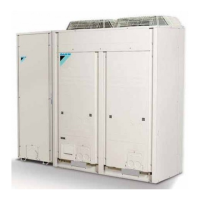
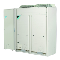
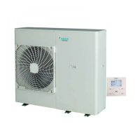
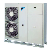
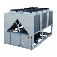
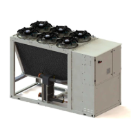
EWAQ080~260DAYN
Packaged air-cooled water chillers
4PW35556-1E
Operation manual
6
Internal wiring - Parts table
Refer to the internal wiring diagram supplied with the unit. The
abbreviations used are listed below:
A01P...................... PCB extension
A02P.............**...... PCB communication (only for option EKACPG)
A4P........................ PCB wired remote controller
A5P...............**...... PCB wired remote controller
(only for option EKRUPG)
A11P,A21P............. PCB main controller circuit 1, circuit 2
A13P,A23P....**...... Frequency inverter circuit 1, circuit 2
(only for option OPIF)
A71P...................... PCB EEV driver
B1PH,B2PH........... High pressure sensor circuit 1, circuit 2
B1PL,B2PL............ Low pressure sensor circuit 1, circuit 2
DS1........................ PCB DIP-switch
E1HS ............## .... Switch box heater with fan
(only for EWAQ130~260 with option OPIF)
E3H...............**...... Heater tape (only for option OP10)
E4H...............**...... Heater tape (only for options OP10, OPSP,
OPHP and OPTP)
E5H...............* ....... Fieldheater
E6H...............**...... Buffertank heater
(only for option OP10 and OPBT)
E7H...............## .... Switch box heater
(only for EWAQ080+100 with option OPIF)
E11HC,E12HC ...... Crankcase heater compressor circuit 1
E21HC,E22HC ...... Crankcase heater compressor circuit 2
(only for EWAQ130~260)
F1~F3 ...........# ...... Main fuses
F1U........................ Fuse PCB
F4,F5 ............# ...... Fuse for heater
F6B........................ Autofuse for primary of TR1
F8B...............**...... Autofuse for switchbox heater
(only for option OPIF)
F9B........................ Autofuse for secondary of TR1
F11B,F12B ............ Autofuse for compressors (M11C, M12C)
(only for EWAQ130~260)
F14B,F24B ............ Autofuse for fanmotors circuit 1, circuit 2
F15B,F25B ...**...... Autofuse for fanmotors circuit 1, circuit 2
(only for option OPIF)
F16B.............## .... Autofuse for pump (K1P) (only for options OPSP,
OPHP, OPTC, OPTP and OPSC)
F17B.............## .... Autofuse for pump (K2P)
(only for options OPTC and OPTP)
F21B,F22B ............ Autofuse for compressors (M21C, M22C)
(only for EWAQ130~260)
H1P~H6P .....*....... Indication lamp for changeable digital outputs
H11P,H12P ............ Indication lamp for operation compressor
circuit 1 C11M, C12M
H21P,H22P ............ Indication lamp for operation compressor
circuit 2 C21M, C22M (only for EWAQ130~260)
HAP~HEP.............. LED PCB
K1A,K2A................ Auxiliary relay for compressor safety circuit 1,
circuit 2
K1P...............## .... Pump contactor (only for options OPSP, OPHP,
OPTC, OPTP and OPSC)
K1R~K22R ............ PCB relay
K1S...............*....... Overcurrent relay pump
K2P...............## .... Pump contactor
(only for options OPTC and OPTP)
K3A........................ Auxiliary relay for heater tape
K11M,K12M........... Compressor contactor for circuit 1
K13F,K14F............. Fancontactor for circuit 1
K13S,K14S............ Fan overcurrent relay for circuit 1
K15F...................... Fancontactor for circuit 1
(only for EWAQ080+100 and EWAQ180~260)
K15S ......................Fan overcurrent relay for circuit 1
(only for EWAQ080+100 and EWAQ180~260)
K16F ......................Fancontactor for circuit 1
(only for EWAQ080+100 and EWAQ240+260)
K16S ......................Fan overcurrent relay for circuit 1
(only for EWAQ080+100 and EWAQ240+260)
K21M,K22M ...........Compressor contactor for circuit 2
(only for EWAQ130~260)
K23F,K24F .............Fancontactor for circuit 2
(only for EWAQ130~260)
K23S,K24S ............Fan overcurrent relay for circuit 2
(only for EWAQ130~260)
K25F ......................Fancontactor for circuit 2
(only for EWAQ180~260)
K25S ......................Fan overcurrent relay for circuit 2
(only for EWAQ180~260)
K26F ......................Fancontactor for circuit 2
(only for EWAQ240+260)
K26S ......................Fan overcurrent relay for circuit 2
(only for EWAQ240+260)
M1P.............. * .......Pump motor 1 (only for options OPSP, OPHP,
OPTC and OPTP)
M2P.............. * .......Pump motor 2
(only for options OPTC and OPTP)
M11C,M12C...........Compressor motors circuit 1
M13F,M14F ............Fan motors circuit 1
M15F......................Fan motors circuit 1
(only for EWAQ080+100 and EWAQ180~260)
M16F......................Fan motors circuit 1
(only for EWAQ080+100 and EWAQ240+260)
M21C,M22C...........Compressor motors circuit 2
(only for EWAQ130~260)
M23F,M24F ............Fan motors circuit 2 (only for EWAQ130~260)
M25F......................Fan motor circuit 2 (only for EWAQ180~260)
M26F......................Fan motor circuit 2 (only for EWAQ240+260)
PE ..........................Main earth terminal
Q1T.............. **......Thermostat (only for option OP10)
Q11C,Q12C ...........Thermal protector compressor circuit 1
(only for EWAQ130)
Q11C,Q12C ...........Electronic protection module compressor
circuit 1 (not for EWAQ130)
Q21C,Q22C ...........Thermal protector compressor circuit 2
(only for EWAQ130)
Q21C,Q22C ...........Electronic protection module compressor
circuit 2 (only for EWAQ150~260)
R1T ........................Ambient temperature sensor
R2T ........................Inlet water temperature sensor
R3T ........................Outlet water temperature sensor
R8T .............. * .......Temperature sensor for changeable analogue
input
R14T ......................Suction temperature sensor circuit 1
R15T,R25T.............Discharge temperature sensor circuit 1
R17T ......................Refrigerant piping temperature sensor circuit 1
R34T ......................Suction temperature sensor circuit 2
(only for EWAQ130~260)
R35T,R45T.............Discharge temperature sensor circuit 2
(only for EWAQ130~260)
R37T ......................Refrigerant piping temperature sensor circuit 2
(only for EWAQ130~260)
S1A~S3A ...............PCB DIP-switch
S1L.........................Flowswitch
S1M........................Main isolator switch
S1PH,S2PH ...........High pressure switch circuit 1, circuit 2
S1S~S5S ..... * .......Switch for changeable digital input
S1T .............. ##.....Thermal contact (only for option OPIF)
S2M.............. #.......Heater tape isolator switch
T1A .............. **......Current transducer (only for option OP57)
 Loading...
