RR+RQ71+100B7V3B + RR+RQ71~125B7W1B
Split System air conditioners
4PW19370-1C
Installation manual
12
WIRING DIAGRAM
A1P............................ Printed circuit board
BS1............................ Push button (forced defrost - pump down)
C1,C2 ........................Capacitor (M1F-M2F)
C3...................... * ..... Capacitor (M1C)
CT.............................. Current transformer (T1A)
DS1............................ Selector switch
E1HC......................... Crankcase heater
F1U,F2U .................... Fuse (T6.3/250 V)
HAP ........................... Light emitting diode (green)
K1M ........................... Magnetic contactor (M1C)
K1R............................ Magnetic relay (K1M)
K2R.................... #..... Magnetic relay (Y2S)
K3R............................ Magnetic relay (E1HC)
K4R............................ Magnetic relay (Y1S)
K5R,K6R,K7R............ Magnetic relay (M1F)
K8R,K9R,K10R.. **.... Magnetic relay (M2F)
M1C........................... Motor (compressor)
M1F,M2F....................Motor (fan)
PC.............................. Power circuit
Q1M,Q2M ..................Thermo switch (M1F-M2F)
Q1RP ................. ##...Phase reverse circuit
R1T ............................Thermistor (air)
R2T ............................Thermistor (coil)
R3T ............................Thermistor (discharge)
RC..............................Signal receiver circuit
S1PH..........................Pressure switch (HIGH)
S1PL ..........................Pressure switch (LOW)
SD..............................Safety devices input
T1A ............................Transformer (220-240 V/24.9 V) (CT)
TC ..............................Signal transmission circuit
X1M,X2M ...................Terminal strip
Y1E ............................Expansion valve (electrical type)
Y1S .................... #.....4-way valve
Y2S ............................Solenoid valve
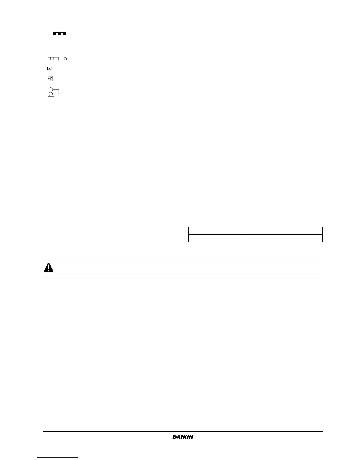
: Field wiring BLK : Black
L: Live BLU : Blue
N: Neutral ORG : Orange
: Ter minal RED : Red
: Connector WHT : White
: Protective earth (screw) YLW : Yellow
: Short circuit connector
,
*: V3 model only # : RQ-unit type only
** : class 125 only ## : W1 model only
NOTE 1: Do not operate the unit by short-circuiting S1PL. This would cause compressor failure.
NOTE 2: Confirm the method of setting selector switches in the service manual. Factory setting of all switches are set to be OFF.
SWITCH BOX (OUTDOOR) :
POSITION OF COMPRESSOR TERMINAL :
WIRE ENTRANCE :
 Loading...