7 Commissioning
Installation manual
13
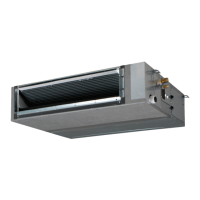
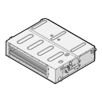
FBA35~140A2VEB9+FBA35~71A2VEB9+ADEA35~125A2VEB
Split system air conditioners
4P456962-1D – 2018.08
Setting content: Then
3
M C1 C2
Airflow adjustment is OFF 11(21) 7 01
Press ON/OFF to return to normal operating
mode.
Possible consequence: The operation lamp
will light up and the unit will start the fan
operation for airflow automatic adjustment.
03
Operation stops after 1 to 8 minutes.
Possible consequence: Setting is finished
and the operation lamp will be off.
02
If there is no change after airflow adjustment, perform the setting
again.
User interface
Check the indoor unit setting: the second code number of mode
11(21) must be set to 01.
Change the second code number according to the external static
pressure of the duct to be connected as in table below.
External static pressure
3
M C1 C2 Class
35 50 60 71 100 125 140
13(23) 6 01 30 30 30 30 40 50 50
02 — — — — — — —
03 30 30 30 30 — — —
04 40 40 40 40 40 — —
05 50 50 50 50 50 50 50
06 60 60 60 60 60 60 60
07 70 70 70 70 70 70 70
08 80 80 80 80 80 80 80
09 90 90 90 90 90 90 90
10 100 100 100 100 100 100 100
11 110 110 110 110 110 110 110
12 120 120 120 120 120 120 120
13 130 130 130 130 130 130 130
14 140 140 140 140 140 140 140
15 150 150 150 150 150 150 150
Time to clean air filter
This setting must correspond with the air contamination in the room.
It determines the interval at which the TIME TO CLEAN AIR FILTER
notification is displayed on the user interface. When using a wireless
user interface, you must also set the address (see the installation
manual of the user interface).
If you want an interval of…
(air contamination)
Then
3
M C1 C2
±2500h (light) 10(20) 0 01
±1250h (heavy) 02
No notification 3 02
▪ 2 user interfaces: When using 2 user interfaces, one must be set
to "MAIN" and the other to "SUB".
7 Commissioning
NOTICE
NEVER operate the unit without thermistors and/or
pressure sensors/switches. Burning of the compressor
might result.
7.1 Checklist before commissioning
After the installation of the unit, first check the following items. Once
all below checks are fulfilled, the unit MUST be closed, ONLY then
can the unit be powered up.
You read the complete installation instructions, as
described in the installer reference guide.
The indoor units are properly mounted.
In case a wireless user interface is used: The indoor unit
decoration panel with infrared receiver is installed.
The outdoor unit is properly mounted.
There are NO missing phases or reversed phases.
The system is properly earthed and the earth terminals
are tightened.
The fuses or locally installed protection devices are
installed according to this document, and have NOT been
bypassed.
The power supply voltage matches the voltage on the
identification label of the unit.
There are NO loose connections or damaged electrical
components in the switchbox.
The insulation resistance of the compressor is OK.
There are NO damaged components or squeezed
pipes on the inside of the indoor and outdoor units.
There are NO refrigerant leaks.
The correct pipe size is installed and the pipes are
properly insulated.
The stop valves (gas and liquid) on the outdoor unit are
fully open.
7.2 To perform a test run
This task is only applicable when using the BRC1E52 or BRC1E53
user interface. When using any other user interface, see the
installation manual or service manual of the user interface.
NOTICE
Do not interrupt the test run.
INFORMATION
Backlight. To perform an ON/OFF action on the user
interface, the backlight does not need to be lit. For any
other action, it needs to be lit first. The backlight is lit for
±30seconds when you press a button.
1 Perform introductory steps.
(3)
Field settings are defined as follows:
▪ M: Mode number – First number: for group of units – Number between brackets: for individual unit
▪ C1: First code number
▪ C2: Second code number
▪ : Default
 Loading...