5 Installation
Installation manual
11
FBA35~140A2VEB9+FBA35~71A2VEB9+ADEA35~125A2VEB
Split system air conditioners
4P456962-1D – 2018.08
2 Check for leaks by applying the bubble test solution to all
connections.
3 Discharge all nitrogen gas.
5.3 Connecting the electrical wiring
DANGER: RISK OF ELECTROCUTION
WARNING
ALWAYS use multicore cable for power supply cables.
WARNING
If the supply cord is damaged, it MUST be replaced by the
manufacturer, its service agent or similarly qualified
persons in order to avoid a hazard.
5.3.1 Specifications of standard wiring
components
Component Class
35+50 60+71 100 125+140
Power supply
cable
MCA
(a)
1.4A 1.3A 3.5A 3.9A
Voltage 220~240V
Phase 1~
Frequency 50/60Hz
Wire sizes Must comply with applicable
legislation
Interconnection cable Minimum cable section of
2.5mm² and applicable for
220~240V
User interface cable Vinyl cord with 0.75 to 1.25mm
2
sheath or cables (2 core wires)
Maximum 500m
Recommended field fuse 16A
Earth leakage circuit breaker Must comply with applicable
legislation
(a) MCA=Minimum circuit ampacity. Stated values are
maximum values (see electrical data of combination with
indoor units for exact values).
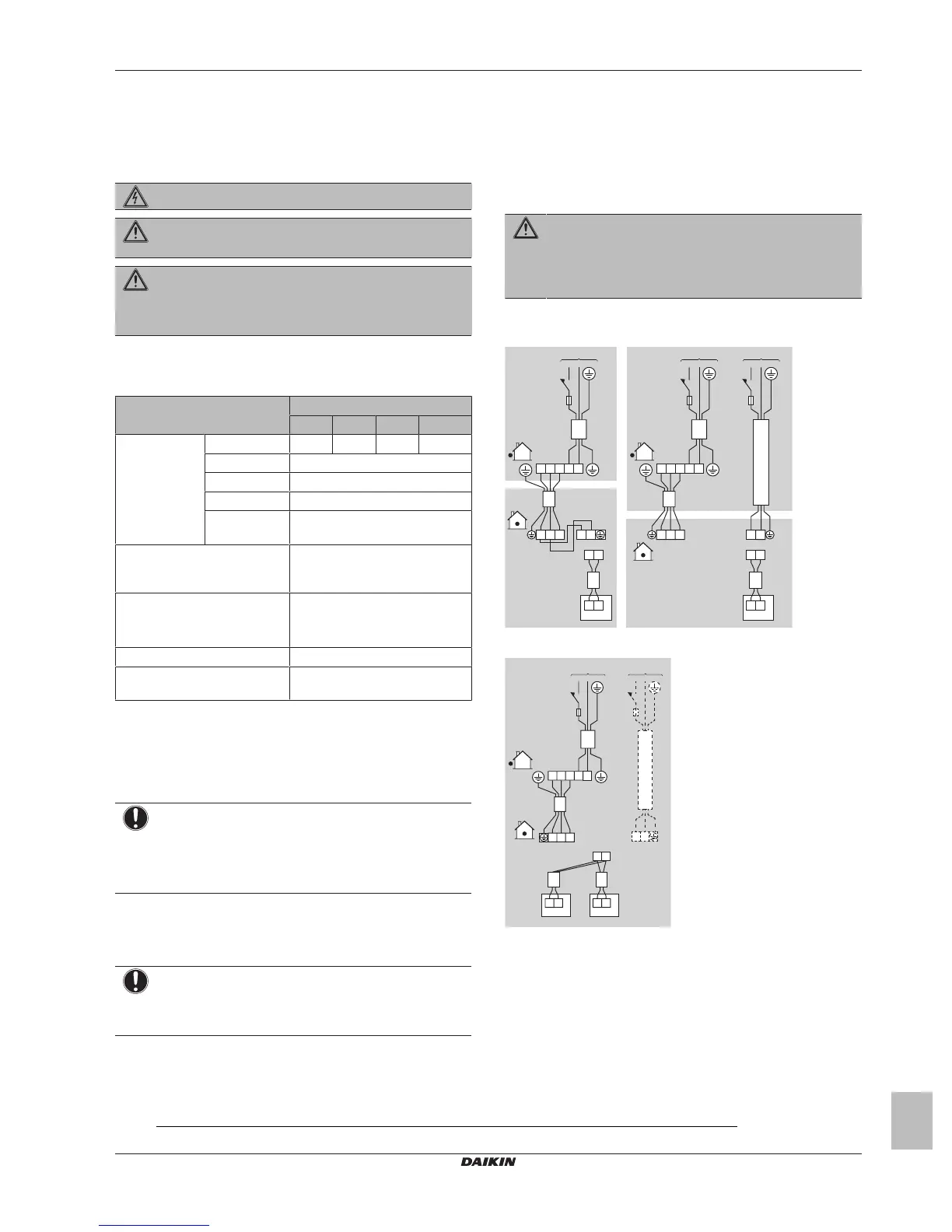
5.3.2 To connect the electrical wiring on the
indoor unit
NOTICE
▪ Follow the wiring diagram (delivered with the unit,
located on the switch box cover).
▪ Make sure the electrical wiring does NOT obstruct
proper reattachment of the service cover.
It is important to keep the power supply and the transmission wiring
separated from each other. In order to avoid any electrical
interference the distance between both wirings should ALWAYS be
at least 50mm.
NOTICE
Be sure to keep the power line and transmission line apart
from each other. Transmission wiring and power supply
wiring may cross, but may NOT run parallel.
1 Remove the service cover.
2 User interface cable: Route the cable through the frame,
connect the cable to the terminal block, and fix the cable with a
cable tie.
3 Interconnection cable (indoor↔outdoor): Route the cable
through the frame, connect the cable to the terminal block
(make sure the numbers match with the numbers on the
outdoor unit, and connect the earth wire), and fix the cable with
a cable tie.
4 Divide the small sealing (accessory) and wrap it around the
cables to prevent water from entering the unit. Seal all gaps to
prevent small animals from entering the system.
WARNING
Provide adequate measures to prevent that the unit can be
used as a shelter by small animals. Small animals that
make contact with electrical parts can cause malfunctions,
smoke or fire.
5 Reattach the service cover.
▪ When using 1 user interface with 1 indoor unit.
1 2 3
a a a
b
c
1 2 3
P
1
P
2
P
1
P
2
d
1 2
L N
3
b
c
b
c
1 2 3
P
1
P
2
P
1
P
2
d
L N L N
L N
▪ When using 2 user interfaces
2
1 2 3
b
c
1 2 3
P
1
P
2
P
1
P
2
P
1
P
2
d d
a
L N
b
c
a
L N
▪ When using group control
2
(2)
Dashed line represents separate power supply.
 Loading...