Check SiUS122226E
226 Part 6 Service Diagnosis
FFQ Series
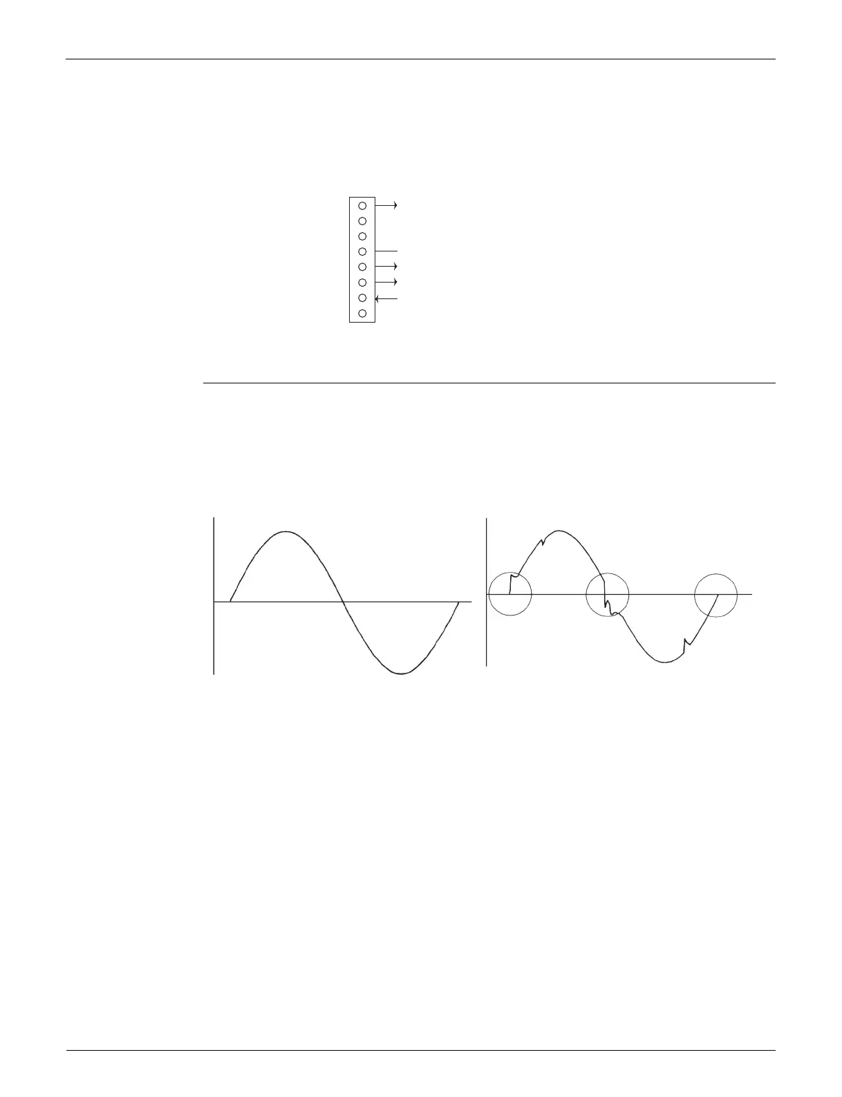
1. Check the connection of connector.
2. Check motor power supply voltage output (pins 5 - 8).
3. Check motor control voltage (pins 5 - 4).
4. Check rotation command voltage output (pins 5 - 3).
8.3 Power Supply Waveform Check
Check No.11 Measure the power supply waveform between No. 1 and No. 2 on the terminal strip, and check the
waveform disturbance.
Check if the power supply waveform is a sine wave (Fig.1).
Check if there is waveform disturbance near the zero-cross (sections circled in Fig.2).
8
7
6
5
4
3
2
1
X20A
(R24373)
Motor power supply voltage (290 ~ 330 VDC)
Unused
Unused
GND
Motor control voltage (15 VDC)
Rotation command voltage (0 ~ 5 VDC)
Rotation pulse input
Unused
[Fig.1] [Fig.2]
(R1736)
(R1444)
 Loading...