Instruction SiBE05-513A
52 System Configuration
5
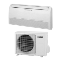
Outdoor Unit
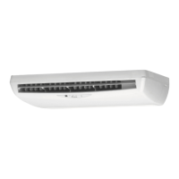
Indoor Unit
1. Louvers (vertical blades):
The louvers are inside of the air outlet.
(page 12.)
2. Air outlet
3. Flap (horizontal blade): (page 12.)
4. Grille tab
5. Air inlet
6. Display
7. Air filter
8. Photocatalytic deodorizing filter or
Air purifying filter:
•
These filters are attached to the inside of the air
filters.
9. Front grille
10. Operation lamp (green)
11. TIMER lamp (yellow): (page 18.)
12. HOME LEAVE lamp (red):
Lights up when you use HOME LEAVE
Operation. (page 16.)
13. Indoor unit ON/OFF switch: (page 10.)
•
Push this switch once to start operation.
Push once again to stop it.
•
The operation mode refers to the following
table.
•
Push the switch using an object with a sharp
tip, such as a pen.
•
This switch is useful when the remote controller
is missing.
14. Signal receiver:
•
It receives signals from the remote controller.
•
When the unit receives a signal, you will hear a
short beep.
•
Operation start .............beep-beep
•
Settings changed..........beep
•
Operation stop ..............beeeeep
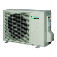
Outdoor Unit
15. Air inlet: (Back and side)
16. Air outlet
17. Refrigerant piping and inter-unit cable
18. Drain hose
19. Earth terminal:
• It is inside of this cover.
Appearance of the outdoor unit may differ from some models.
17
18
19
16
15
Mode
Temperature
setting
Air flow
rate
FLKS COOL
22 C°
°
AUTO
FLXS AUTO
25 C
AUTO

 Loading...