DAMA-SM-21-001 Wiring Diagrams
Appendix 112
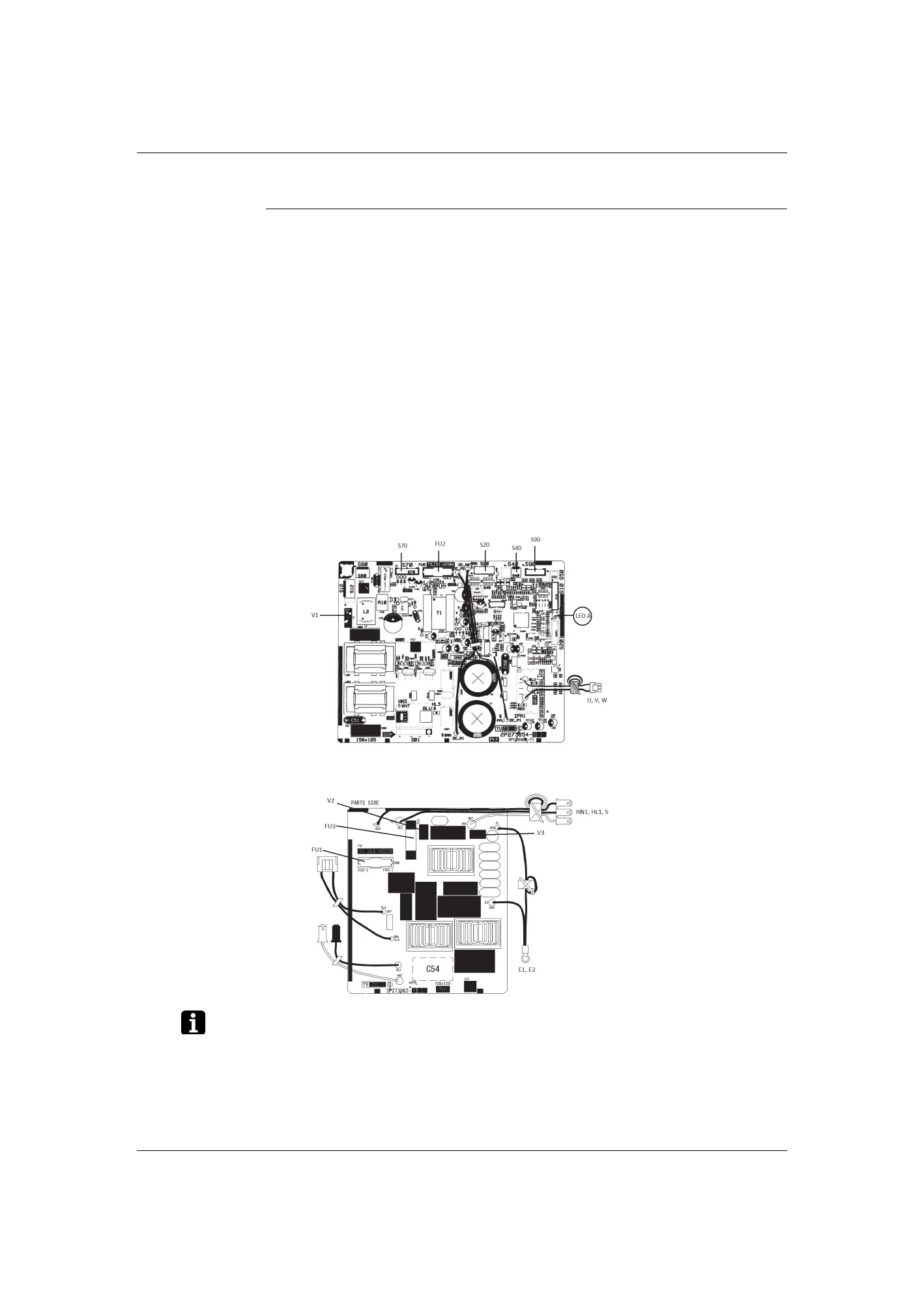
2.4.2 18/24 Class
Main PCB (A1P)
The symbols in the parenthesis are the names on the appropriate wiring diagram.
1) S20 Connector for electronic expansion valve coil
2) S40 Connector for overload protector
3) S70 Connector for DC fan motor
4) S90 Connector for thermistors (outdoor temperature,
outdoor heat exchanger, discharge pipe
temperature)
5 HL1, HN1, S Connector for terminal strip
6) E1, E2 Terminals for earth wire
7) U, V, W Connector for compressor
8) FU1 (F1U),
FU2 (F2U)
Fuse (3.15 A, 250 V)
9) FU3 (F3U) Fuse (30 A, 250 V)
10) LED A LED for service monitor (green)
11) V1 (R1V),
V2 (R2V),
V3 (R3V)
Varistor
 Loading...