Do you have a question about the Daikin FTXG-J and is the answer not in the manual?
Lists all functions available for the indoor and outdoor units.
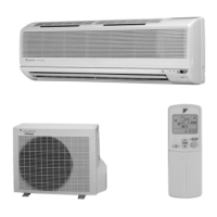
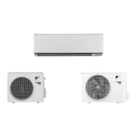
Details technical specifications for indoor and outdoor units, including capacity, power, dimensions, etc.
Shows connector locations and functions on the indoor unit's control PCB.
Details connector locations on the outdoor unit's main PCB for 25/35 class models.
Describes primary functions like temperature control, frequency principle, and operation modes.
Explains the role and function of various thermistors in the system's operation.
Details control specifications, including mode hierarchy and specific control strategies.
Details the operation and features of the remote controller for specific models.
Explains how to diagnose issues using LED indicators on indoor and outdoor units.
Lists common problems and their corresponding troubleshooting steps and measures.
Describes methods to access service check modes and interpret error codes using the remote controller.
Provides detailed error codes, their descriptions, and reference pages for troubleshooting.
Explains the procedure for pump down operation, essential for unit relocation or disposal.
Details the procedure and conditions for activating forced cooling operation.
Describes how to perform trial operation to ensure all functions work correctly.
Covers settings required for specific installation scenarios, like multiple units or special conditions.
Explains the correct application of silicon grease when replacing PCBs for heat dissipation.
Provides schematic diagrams illustrating the refrigerant piping for indoor and outdoor units.
Presents electrical wiring diagrams for the indoor and outdoor units, showing component connections.
Lists references to separate booklets containing detailed removal procedures for specific models.
| Cooling Capacity | 2.5 kW |
|---|---|
| Heating Capacity | 3.2 kW |
| Energy Efficiency Rating (Cooling) | A+++ |
| Energy Efficiency Rating (Heating) | A++ |
| Noise Level (Indoor) | 19 dB(A) |
| Power Supply | 220-240V / 50Hz |
| Outdoor Unit Dimensions (HxWxD) | 550 x 765 x 285 mm |