Do you have a question about the Daikin FTK Series and is the answer not in the manual?
Critical safety warnings and precautions for technicians and users during operation and repair.
Explains the meaning of various icons used throughout the manual for clarity.
Details the versions and modifications made to the service manual.
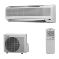
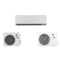
Lists the specific Daikin FTK(X) series models covered by this manual.
Provides detailed technical specifications for indoor and outdoor units, including performance and dimensions.
Lists and briefly describes the operational functions available for the various models.
Details core functions like temperature control, frequency control, and airflow management.
Explains the role of different thermistors in system monitoring and control operations.
Outlines control logic, mode hierarchy, protection functions, and operational parameters.
Quick reference for common operational issues and initial diagnostic checks.
Guides users to diagnose faults using LED indicators on the indoor and outdoor units.
Instructions for accessing and interpreting error codes displayed on the remote controller.
Comprehensive fault-finding procedures for various error codes and system malfunctions.
Step-by-step checks for actuators like thermistors, valves, and motors to diagnose faults.
Procedure for safely recovering refrigerant before unit relocation or disposal.
Method for manually initiating cooling operation for maintenance or specific tests.
Guidance on proper application of silicone grease for heat dissipation on PCBs.
Visual representation of refrigerant circuit layouts for various indoor and outdoor units.
Electrical schematics illustrating connections for indoor and outdoor units and their components.
Graphical representation of the operational temperature and humidity limits for the air conditioner.
| Refrigerant | R32 |
|---|---|
| Series | FTK |
| Cooling Capacity | 2.5 kW - 7.1 kW |
| Heating Capacity | 2.5 kW - 8.0 kW |
| Power Supply | 220-240 V, 50 Hz |
| Noise Level (Indoor Unit) | 19 dB(A) - 45 dB(A) |