EasyManua.ls Logo

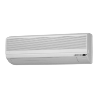
Daikin FTK25BVMB User Manual

Daikin FTK25BVMB
201 pages
To Next Page IconTo Next Page
Page #1 background imageLoading...
Page #1 background image
SiBE04-302
Inverter Pair
Wall Mounted Type
B Series
[Applied Models]
z
zz
zInverter Pair : Cooling Only
z
zz
zInverter Pair : Heat Pump
Service
Manual

Table of Contents

Other manuals for Daikin FTK25BVMB

Questions and Answers:

Daikin FTK25BVMB Specifications

General IconGeneral
Cooling Capacity2.5 kW
Heating Capacity3.2 kW
Energy Efficiency Ratio (EER)3.21
Power Supply220-240V, 50Hz
Indoor Unit Dimensions (W x H x D)800 x 290 x 230 mm
Outdoor Unit Dimensions (W x H x D)800 x 540 x 300 mm
RefrigerantR32
TypeSplit
Energy Efficiency Ratio (Cooling)3.21 W/W
Indoor Unit Weight8 kg
Outdoor Unit Weight22 kg

Summary

Part 1 List of Function

Introduction

General introduction to the manual and its sections.

Functions

Lists functions applicable to different models, categorized by Cooling Only and Heat Pump.

Part 2 Specifications

Specifications

Detailed technical specifications for the air conditioner models.

Part 3 Printed Circuit Board Connector Wiring Diagram

Printed Circuit Board Connector Wiring Diagram

Diagrams illustrating the connectors and wiring of the printed circuit boards.

Part 4 Function and Control

Main Functions

Overview of the unit's primary operational functions and their principles.

Control Specification

Technical details and logic for the unit's control systems.

Part 5 System Configuration

System Configuration

Explains the overall system setup, operation, and user instructions.

Instruction (In case of FTK(X)S 25/35 BVMB)

Specific instructions and safety precautions for certain models.

Part 6 Service Diagnosis

Caution for Diagnosis

Important warnings and guidelines to follow before starting diagnostic procedures.

Troubleshooting

Detailed steps and flowcharts for diagnosing and resolving various operational issues.

Part 7 Removal Procedure

Indoor Unit

Step-by-step procedures for disassembling and removing parts of the indoor unit.

Outdoor Unit

Step-by-step procedures for disassembling and removing parts of the outdoor unit.

Part 8 Others

Explanation

General explanations of unit features and operations, including test runs.

Part 9 Appendix

Piping Diagrams

Schematics illustrating the refrigerant piping configurations for indoor and outdoor units.

Wiring Diagrams

Electrical wiring diagrams for indoor and outdoor units.

Related product manuals