Do you have a question about the Daikin FTXB09AXVJU and is the answer not in the manual?
General safety guidelines and warnings to be observed before conducting repair work.
Specific safety precautions to be taken during repair procedures, including electrical and refrigerant hazards.
Explanation of how room temperature is detected and set temperature is controlled via thermistors.
Details on how the system operates in Cool, Heat, Fan, Auto, and Dry modes, with compressor logic.
Details the function of various thermistors (discharge pipe, heat exchanger, indoor, outdoor air) in controlling operations.
Controlling compressor rotation within zones (stop, drop, keep, up, reset) for protection and performance.
How defrosting is performed using the cooling cycle and conditions for starting and terminating defrost.
Protection mechanism that reduces compressor frequency when indoor coil temperature drops below a threshold.
Adjusting compressor frequency based on coil temperature to prevent high pressure in the system.
Using discharge pipe temperature to control compressor frequency and prevent overheating.
Monitoring and restricting compressor rotation based on overall current to prevent circuit breaker overload.
Determining compressor frequency based on room thermistor and target temperature differences.
Explanation of LED indicators on the indoor unit for different operating modes and fault indications.
Details LED color changes and blinking patterns for different running conditions and errors on FTK(X)B models.
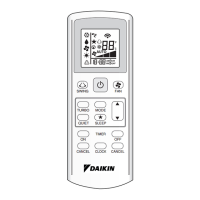
Procedure to retrieve error codes using remote controller models BRC52A and BRC52B.
Instructions for operating the remote controller to display error codes and retrieve last state errors.
Table listing error codes (00, A1, A5, etc.) and their corresponding descriptions for inverter models.
Troubleshooting steps for A1 error, including checking PCB, connectors, and replacement.
Troubleshooting steps for E5 error, checking refrigerant, valves, thermistors, and PCB.
Troubleshooting steps for E6 error, involving compressor lock, harness, and PCB checks.
Troubleshooting steps for E7 error, checking fan motor, connectors, foreign matter, and PCB.
Troubleshooting steps for E8 error, measuring input current and checking fan motor, PCB, and compressor.
Troubleshooting steps for EA error, checking thermistors, valve coil, harness, and refrigerant.
Troubleshooting steps for F3 error, checking thermistors, EXV, refrigerant line, and PCB.
Troubleshooting steps for F6 error, checking installation space, fan, EXV, thermistor, and PCB.
Troubleshooting steps for thermistor errors, checking connections, resistance, and relevant components.
Troubleshooting steps for U0 error, checking valves, thermistors, EXV, refrigerant charge, and leakage.
Procedures to check for short circuits in power transistor and main circuit components.
Procedure to check power supply waveform for sine wave and disturbances using an oscilloscope.
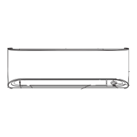
| Type | Wall Mounted |
|---|---|
| Cooling Capacity | 2.5 kW |
| Heating Capacity | 3.2 kW |
| Energy Efficiency Ratio (Cooling) | 3.21 |
| HSPF | 3.8 |
| Refrigerant | R-32 |
| Power Supply | 220-240V, 50Hz |
| Sound Level (Indoor) | 19 dB |
| Cooling Capacity (BTU) | 9000 BTU/h |