EasyManua.ls Logo

Daikin FTXB24AXVJU User Manual

Daikin FTXB24AXVJU
84 pages
To Next Page IconTo Next Page
Page #1 background imageLoading...
Page #1 background image
SERVICE MANUAL
Inverter Wall Mounted Single Split
dd
SM-5WM-Y-NA-B1
MODELS
Cooling Only
FTKB09AXVJU RKB09AXVJU
FTKB12AXVJU RKB12AXVJU
FTKB18AXVJU RKB18AXVJU
FTKB24AXVJU RKB24AXVJU
FTKN09AXVJU RKN09AXVJU
FTKN12AXVJU RKN12AXVJU
FTKN18AXVJU RKN18AXVJU
FTKN24AXVJU RKN24AXVJU
Heatpump
FTXB09AXVJU RXB09AXVJU
FTXB12AXVJU RXB12AXVJU
FTXB18AXVJU RXB18AXVJU
FTXB24AXVJU RXB24AXVJU
FTXN09AXVJU RXN09AXVJU
FTXN12AXVJU RXN12AXVJU
FTXN18AXVJU RXN18AXVJU
FTXN24AXVJU RXN24AXVJU
Question and Answer IconNeed help?

Do you have a question about the Daikin FTXB24AXVJU and is the answer not in the manual?

Daikin FTXB24AXVJU Specifications

General IconGeneral
Cooling Capacity2.4 kW
Heating Capacity3.2 kW
RefrigerantR-32
Coefficient of Performance (COP)3.6
TypeSplit System
Power Supply220-240V, 50Hz

Summary

Safety Cautions

Caution and Warnings

Important safety instructions before conducting repair work.

Caution in Repair

Safety precautions to be taken during repair work.

Cautions Regarding Products after Repair

Inspection after Repair

1.0 Inverter Single Split

1.1 Product line-up

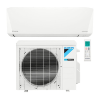
Details the various models in the Inverter Single Split product range.

1.2 Printed Circuit Board (PCB) Connector Wiring Diagram

1.2.1 Indoor PCB

Wiring details for the Indoor PCB for specific models.

1.2.2 Indoor PCB

1.2.3 Outdoor PCB

1.2.4 Outdoor PCB

1.3 Piping Length & Elevation

1.4 Outline & Dimension

1.4.1 Indoor Unit

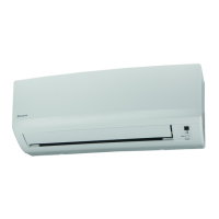
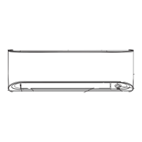
Dimensions and outlines for the Indoor Unit of specific models.

1.4.2 Outdoor Unit

1.5 Engineering Data

1.5.1 Cooling Only

Engineering specifications for cooling-only models.

1.5.2 Heatpump

2.0 Function & Control

3.0 Service Diagnosis

3.1 Error Indication from Indoor

How to interpret LED indicators on the indoor unit for operational status and errors.

3.2 Error Code retrieved by remote controller

3.2.1 Remote controller model BRC52A & BRC52B

Guide to retrieving error codes using specific remote controller models.

3.3 Error code description for Inverter

A1 INDOOR PCB ABNORMALITY

A5 ANTIFREEZE PROTECTION OR HIGH PRESSURE CONTROL

A6 INDOOR FAN MOTOR ABNORMALITY

C4 INDOOR HEAT EXCHANGER THERMISTOR ABNORMALITY

C9 INDOOR ROOM THERMISTOR ABNORMALITY

E1 OUTDOOR PCB ABNORMALITY

E5 COMPRESSOR OVERLOAD

E6 COMPRESSOR LOCK/START-UP ABNORMALITY

E7 OUTDOOR FAN MOTOR LOCK

E8 AC INPUT OVER CURRENT

EA 4 WAY VALVE ABNORMALITY

F3 DISCHARGE PIPE OVERHEAT

F6 HEAT EXCHANGER OVERHEAT

H0 (Class 18/24) COMPRESSOR SENSOR SYSTEM ABNORMAL

H0 (Class 09/12) COMPRESSOR SENSOR SYSTEM ABNORMAL

H6 (Class 09/12) POSITION SENSOR ABNORMAL (COMPRESSOR)

H6 (Class 18/24) POSITION SENSOR ABNORMAL (COMPRESSOR)

H8 AC CURRENT SENSOR ABNORMALITY

H9, J3, J6, P4 Thermistor or related abnormality

L3 ELECTRICAL BOX TEMPERATURE RISE (COMPRESSOR OFF)

L4 Heat sink overheat

L5 IPM ABNORMALITY

U0 INSUFFICIENT GAS

U2 DC VOLTAGE OUT OF RANGE

U4 COMMUNICATION ABNORMALITY

UA INSTALLATION ABNORMALITY

4.0 Wiring Connection

5.0 Refrigerant Diagram

6.0 Appendix A:

6.10 Trial Operation and Field Settings

Related product manuals