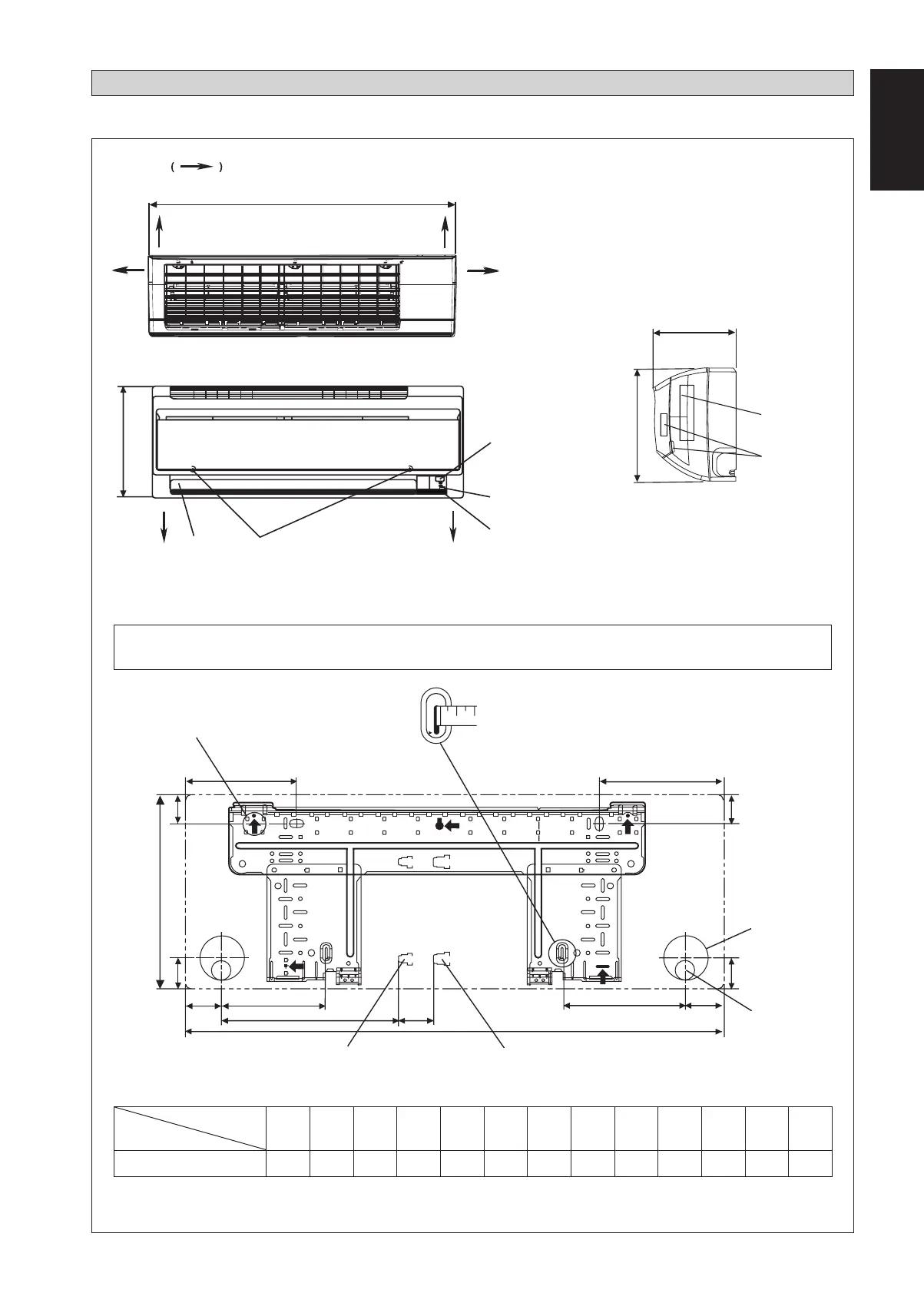
NOTE: PLEASE BASED ON ACTUAL INSTALLATION PLATE DESIGN IN THE UNIT FOR INSTALLATION PLATE
25/35 DIMENSION REFERENCE AT PAGE 1&2.
English
1-1
Indoor Unit [FTXN]
A
B
FRONT VIEW
TOP VIEW
C
SIDE VIEW
H
I
B
THE MARK SHOWS PIPING DIRECTION
REAR REAR
RIGHTLEFT
BOTTOM
BOTTOM
FRONT GRILLE FIXED SCREWS
(INSIDE)
LOUVER
SIGNAL RECEIVER
INDOOR UNIT
ON/OFF SWITCH
ROOM TEMPERATURE
THERMISTOR (INSIDE)
NAME PLATE
TERMINAL
BLOCK
WITH EARTH
TERMINAL
F
E
J
G
G
L
D
B
K
M
A
Gas pipe end
INSTALLATION PLATE 25/35
Liquid pipe end
Through the wall
hole Ø 65mm
All dimensions are in mm
Drain hose position
F
OUTLINE AND DIMENSIONS
«
Recommended mounting plate retention spots
(5 spots in all)
Use tape measure as shown.
Position the end of a tape measure at
Ñ
Original Instruction
Dimension
Model
ABCDEFGH I JKLM
25/35
800 288 204 166 184 42 46 55 56 154 182 263 52
1 IM-5WMYJ-0214(0)DK_EN-39282.in1 11 IM-5WMYJ-0214(0)DK_EN-39282.in1 1 3/10/14 1:59:22 PM3/10/14 1:59:22 PM
 Loading...