SiENBE12-713 Instruction
System Configuration 121
"
Outdoor Unit
"
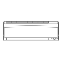
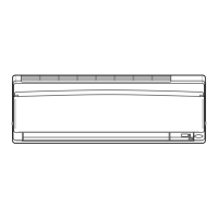
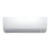
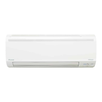
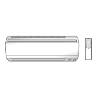
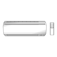
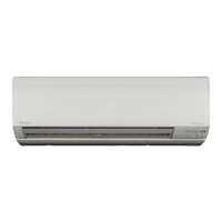
Indoor Unit
"
Outdoor Unit
Appearance of the outdoor unit may differ from some models.
1. Air outlet
2. Air outlet grille:
• (Field supply) Appearance of the Air inlet
grille may differ with some models.
3. Display, Control panel
4. Suction grille:
• (option) Appearance of the Air outlet grille
an Air inlet grille may differ with some
models.
5. Air inlet
6. Room temperature sensor:
• The louvers are inside of the air outlet.
7. Operation lamp (green)
8. TIMER lamp (Yellow)
9. HOME LEAVE lamp (red):
• Lights up when you use HOME LEAVE
operation.
10. Indoor Unit ON/OFF switch:
• Push this switch once to start operation.
Push once again to stop it.
• This switch is useful when the remote
control is missing.
•
the operation mode refers to the
following table
.
11. Air inlet:
(Back and side)
12. Refrigirant piping and inter-unit cable
13. Drain hose
14. Earth terminal:
• It is inside of this cover.
15. Air outlet
Mode Temperature
setting
Air flow
rate
F(C)DKS COOL 22°C AUTO
F(C)DXS AUTO 25°C AUTO
 Loading...