EasyManua.ls Logo

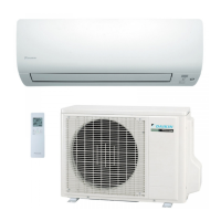
Daikin FTXS35BVMB User Manual

Daikin FTXS35BVMB
201 pages
To Next Page IconTo Next Page
Page #1 background imageLoading...
Page #1 background image
SiBE04-302
Inverter Pair
Wall Mounted Type
B Series
[Applied Models]
z
zz
zInverter Pair : Cooling Only
z
zz
zInverter Pair : Heat Pump
Service
Manual

Table of Contents

Questions and Answers:

Daikin FTXS35BVMB Specifications

General IconGeneral
BrandDaikin
ModelFTXS35BVMB
CategoryAir Conditioner
LanguageEnglish

Summary

Service Manual

Inverter Pair Wall Mounted Type B Series

Identifies the specific product series covered by the manual.

Part 1 List of Function

1.1 Safety Cautions

Details essential safety precautions for handling and operation.

Part 2 Specifications

Part 3 Printed Circuit Board Connector Wiring Diagram

1. Printed Circuit Board Connector Wiring Diagram

Illustrates the wiring and connections of circuit boards.

Part 4 Function and Control

1. Main Functions

Describes the primary operational functions of the system.

Part 5 System Configuration

2.1 Safety Precautions

Essential safety precautions for installation and initial operation.

2.12 Trouble Shooting

Offers solutions for common operational issues and errors.

Part 6 Service Diagnosis

1. Caution for Diagnosis

Important cautions before performing diagnostic procedures.

2. Problem Symptoms and Measures

Lists common problems and their corresponding solutions.

4. Troubleshooting

Provides a comprehensive guide to troubleshooting system faults.

4.1 Error Codes and Description

Explains error codes displayed and their meanings.

4.2 Indoor Unit PCB Abnormality

Diagnoses and addresses abnormalities with the indoor unit PCB.

4.3 Freeze-up Protection Control or High Pressure Control

Troubleshooting freeze-up or high pressure control issues.

4.18 Insufficient Gas

Troubleshooting insufficient gas conditions.

Part 7 Removal Procedure

1. Indoor Unit

Procedures for removing components from the indoor unit.

1.4 Removal of Switch Box, PC Board and Swing Motor

Steps to remove the switch box, PC board, and swing motor.

1.5 Removal of Heat Exchanger

Procedure for removing the heat exchanger.

1.7 Removal of Fan Rotor and Fan Motor

Steps to remove the fan rotor and fan motor.

2.8 Removal of Compressor

Steps for removing the compressor.

Related product manuals