■English 9
Outdoor Unit
1.
Installing outdoor unit.
• For outdoor unit installation, see Choosing a Site and Indoor/Outdoor Unit Installation Drawings.
2.
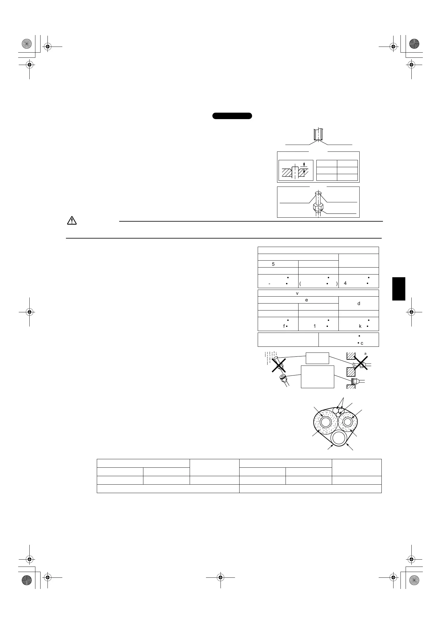
Flaring the pipe end.
1) Cut the pipe end with a pipe cutter.
2) Remove burrs with the cut surface facing downward so that the
chips do not enter the pipe.
3) Put the flare nut on the pipe.
4) Flare the pipe.
5) Check that the flaring is properly made.
WARNING
1) Incomplete flaring may cause refrigerant gas leakage.
3.
Refrigerant piping.
1) Align the centres of both flares and tighten the flare nuts 3 or 4
turns by hand. Then tighten them fully with the torque wrenches.
• Use torque wrenches when tightening the flare nuts to prevent
damage to the flare nuts and escaping gas.
2) To prevent gas leakage, apply refrigeration machine oil on both
inner and outer surfaces of the flare. (Use refrigeration oil for R22)
3-1. Caution on piping handling.
1) Protect the open end of the pipe against dust and moisture.
2) All pipe bends should be as gentle as possible. Use a pipe
bender for bending.
(Bending radius should be 30 to 40mm or larger.)
3-2. Selection of copper and heat insulation materials.
• When using commercial copper pipes and fittings, observe the following:
1) Insulation material: Polyethylene foam
Heat transfer rate: 0.041 to 0.052W/mK (0.035 to 0.045kcal/mh°C)
Refrigerant gas pipe’s surface temperature reaches 110°C max.
Choose heat insulation materials that will withstand this temperature.
2) Be sure to insulate both the gas and liquid piping and to provide insulation
dimensions as below.
3) Use separate thermal insulation pipes for gas and liquid refrigerant pipes.
Gas side
Liquid side
Gas pipe thermal insulation
Liquid pipe
thermal insulation
25 class 35 class 25 class 35 class
O.D. 9.5mm O.D. 12.7mm O.D. 6.4mm I.D. 12-15mm I.D. 14-16mm I.D. 8-10mm
Thickness 0.8mm Thickness 10mm Min.
Outdoor unit
A
A
RIGID
IMPERIAL
Die
Check
Flare’s inner
surface must
be flaw-free.
The pipe end must
be evenly flared in
a perfect circle.
Make sure that the
flare nut is fitted.
Set exactly at the position shown below.
Flaring
(Cut exactly at
right angles.) Remove burrs
0.5mm
1.0mm
Flare nut tightening torque
Service port cap 10.8-14.7N
l
m
tightening torque (110-150kgf
l
cm)
35 class
1/2 inch
49.5-60.3N
l
m
(505-615kgf
l
cm)
Liquid side
1/4 inch
14.2-17.2N
l
m
(144-175kgf
l
cm)
25 class
3/8 inch
32.7-39.9N
l
m
(330-407kgf
l
cm)
Valve cap tightening torque
35 class
1/2 inch
48.1-59.7N
l
m
(490-610kgf
l
cm)
Liquid side
1/4 inch
21.6-27.4N
l
m
(220-280kgf
l
cm)
Gas side
25 class
3/8 inch
21.6-27.4N
l
m
(220-280kgf
l
cm)
Gas side
Wall
If no flare cap is
available, cover the
flare mouth with
tape to keep dirt or
water out.
Be sure to
place a cap.
Rain
Gas pipe
Liquid pipe
Gas pipe
insulation
Liquid pipe
insulation
Finishing tape
Drain hose
Inter-unit wiring
Thermistor cable
01_EN_3P211822-2C.fm Page 9 Tuesday, November 27, 2007 6:31 PM
 Loading...