12 Technical data
Installation manual
13
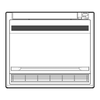
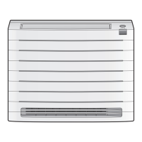
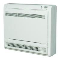
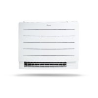
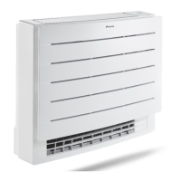
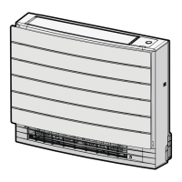
CVXM-A, FVXM-A, CVXM-A9, FVXM-A9, FVXTM-A
Split system air conditioners
3P477070-2P – 2022.09
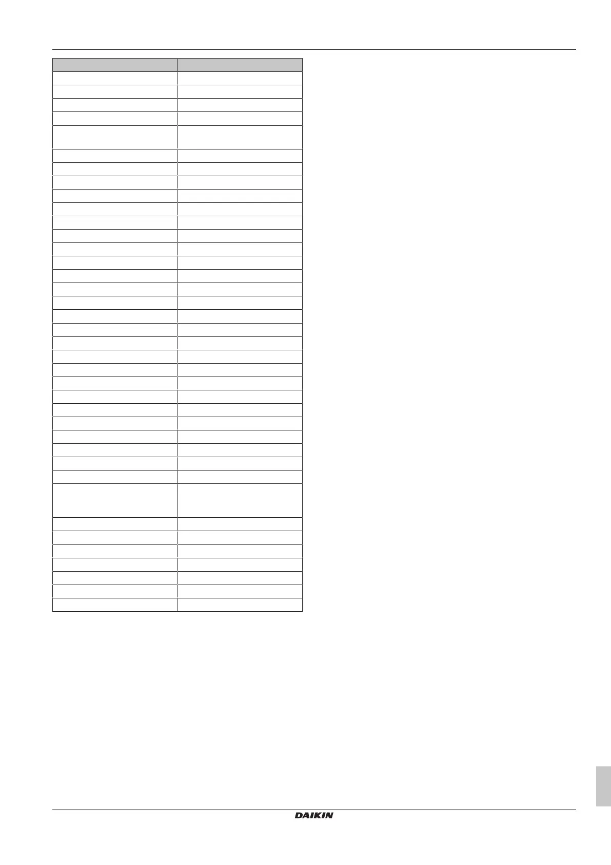
Symbol Meaning
PCB* Printed circuit board
PM* Power module
PS Switching power supply
PTC* PTC thermistor
Q* Insulated gate bipolar transistor
(IGBT)
Q*C Circuit breaker
Q*DI, KLM Earth leak circuit breaker
Q*L Overload protector
Q*M Thermo switch
Q*R Residual current device
R* Resistor
R*T Thermistor
RC Receiver
S*C Limit switch
S*L Float switch
S*NG Refrigerant leak detector
S*NPH Pressure sensor (high)
S*NPL Pressure sensor (low)
S*PH, HPS* Pressure switch (high)
S*PL Pressure switch (low)
S*T Thermostat
S*RH Humidity sensor
S*W, SW* Operation switch
SA*, F1S Surge arrester
SR*, WLU Signal receiver
SS* Selector switch
SHEET METAL Terminal strip fixed plate
T*R Transformer
TC, TRC Transmitter
V*, R*V Varistor
V*R Diode bridge, Insulated-gate
bipolar transistor (IGBT) power
module
WRC Wireless remote controller
X* Terminal
X*M Terminal strip (block)
Y*E Electronic expansion valve coil
Y*R, Y*S Reversing solenoid valve coil
Z*C Ferrite core
ZF, Z*F Noise filter
 Loading...