Installation manual
7
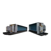
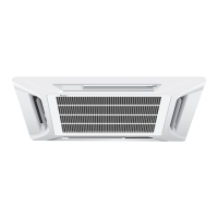
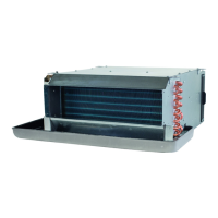
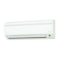
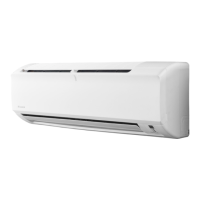
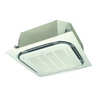
FWC
Fan coil units
4PW64525-1B – 2014.03
Install the fan coil unit
4.5.3. Fill the water circuit
During filling, it might not be possible to remove all air in the system.
Remaining air can be removed during the first operating hours of the
unit. The air can be removed from the unit through the manual air
purge valve. For the location of the air purge valve on the unit, refer to
figure 6: “Water piping connection”.
1 Open the air purge valve (refer to figure “Air purge valve”) by
turning the nut 2 times.
2 Push the springy core (refer to figure “Air purge valve”) to let off
superfluous air from the unit water circuit(s).
3 Close the nut.
4 Additional filling with water afterwards might be required (but
never through the air purge valve).
Fig. 4.6: Air purge valve
Install the fan coil unit
4.6. Connect the electrical wiring
Precautions
Observe the notes mentioned below when connecting the electrical
wiring.
Q Do not connect wires of different gauge to the same power supply
terminal. Looseness in the connection may cause overheating.
Q Do not connect wires of different gauge to the same grounding
terminal. Looseness in the connection may deteriorate the
protection.
Q When connecting wires of the same gauge, connect them
according to the figure “Terminal Wiring”.
Fig. 4.7: Terminal wiring
Q Use the specified electric wire (refer to “Field wiring
specifications” on page 4). Connect the wire securely to the
terminal. Lock the wire down without applying excessive force to
the terminal. Use the appropriate tightening torque:
Table 4.1: Tightening torque
Q Remote controller wiring should be located at least 50 mm away
from the unit transmission wiring and other wiring. Failure to
observe this guideline may result in malfunction due to electrical
noise.
Q For the remote controller wiring, refer to the installation manual of
the remote controller delivered with the remote controller.
Q Keep wiring in neat order so that wires do not obstruct other
equipment or force the control box cover to pop open. Make sure
the cover closes tight. Incomplete connections could result in
overheating, and in the worst case, electric shock or fire.
Wiring diagram
Refer to the wiring diagram sticker on the unit (on the inside of the
control box cover).
Wired remote controller
Wireless remote controller (Receiver/display unit)
Notice
Water quality must be according to EU directive 98/83 EC.
Notice
Use of glycol is allowed, but the amount shall not exceed
40% of the volume. A higher amount of glycol may cause
damage to the hydraulic components.
a Air purge
b Nut
c Springy core
Tightening torque (N·m)
Terminal block for remote controller 0.79~0.97
Terminal block for power supply 1.18~1.44
Notice
Never connect the unit transmission wiring to the remote
controller wiring. This connection could cause irreparable
damage to the entire system.
: Terminal RED : Red YLW : Yellow
: Connector BLK : Black GRN : Green
: Field wiring WHT : White BLU : Blue
ORG : Orange BRN : Brown
GRY : Grey PNK : Pink
A1P,
A2P
Printed circuit board
C1 Capacitor
F1U Fuse
HAP Light emitting diode (service monitor green)
KPR Magnetic relay (M1P)
L1 Coil
M1F Motor (indoor fan)
M1P Motor (drain pump)
M1S Motor (swing flap)
PS Power supply circuit
Q1D1 Earth leak detector
R1T Thermistor (air)
R2T,
R3T
Thermistor
S1L Float switch
X1M,
X2M
Terminal strip
Z1F Ferrite core
R1T Thermistor (air)
SS1 Selector switch (main/sub)
A3P,
A4P
Printed circuit board
BS1 Push button (ON/OFF)
H1P Light emitting diode (ON - red)
H2P Light emitting diode (timer - green)
 Loading...