Installation manual
1
FWC
Fan coil units
4PW64525-1B – 2014.03
Introduction
Table of contents
Table of contents
Introducti onIntroducti on
1 Introduction
Introduction
1.1. About fan coil units
A fan coil unit provides heating and/or cooling to individual spaces. It
creates a comfortable environment in both commercial and residential
applications. Fan coil units are widely used for the air conditioning of
offices, hotels and houses.
The main components of fan coil units are:
Q a fan,
Q a heat exchanger.
The heat exchanger receives hot or cold water from a heating or
cooling source.
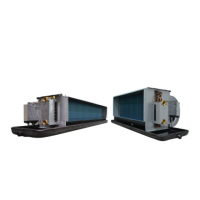
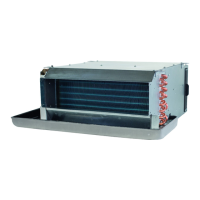
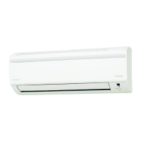
DAIKIN offers a wide range of fan coil units for both concealed and
exposed applications. Contact your DAIKIN dealer for a list of related
products.
Introduction
1.2. About this fan coil unit
The model identification code means:
The following models are available:
Q FWC06-07-08-09B7TV1B
2-pipe fan coil units have a single-circuit heat exchanger. The
device can be used for either cooling or heating.
Q FWC06-07-08-09B7FV1B
4-pipe fan coil units have a double-circuit heat exchanger. The
units can be connected to both cooling and heating systems. Use
this type if you have a separate source for cooling and for
heating.
Introduction
1.3. About this document
This document is an installation manual. It is intended for the installer
of this product. It describes the procedures for installing,
commissioning and maintaining the unit, and it will provide help if
problems occur. Carefully read the relevant parts of the manual.
How to get the manual?
Q A printed version of the manual is delivered with the unit.
Q Contact your local DAIKIN dealer for an electronic version of the
manual.
For detailed instructions about how to install and operate the
associated products and/or optional equipment, refer to the relevant
catalogues, technical literature or product manuals for those products.
The original documentation is written in English. All other languages
are translations of the original documentation.
Introduction
1 Introduction 1
1.1. About fan coil units 1
1.2. About this fan coil unit 1
1.3. About this document 1
1.3.1. Meaning of warnings and
symbols
2
2 Precautions for installation 2
3 Prepare the installation of the fan coil
unit
2
3.1. Check that you have all optional
equipment
2
3.2. Verify the appropriate installation
location
3
3.3. Prepare the installation space 3
3.4. Prepare the water piping work 3
3.5. Prepare the electrical wiring work 4
3.6. Prepare the installation of optional
equipment
4
4 Install the fan coil unit 4
4.1. Unpack the unit 4
4.2. Check if all accessories are included 5
4.3. Prepare the ceiling opening 5
4.4. Fix the unit 5
4.5. Perform the water piping work 6
4.5.1. Connect the water pipes 6
4.5.2. Insulate the water pipes 6
4.5.3. Fill the water circuit 7
4.6. Connect the electrical wiring 7
4.6.1. Connect the power supply 8
4.6.2. Connect the remote controller
and unit transmission wiring
8
4.6.3. Close the control box 8
4.7. Perform the drain piping work 8
4.7.1. Install the drain piping in the
building
8
4.7.2. Connect the drain piping to the
unit
9
4.7.3. Test the drain piping 9
4.8. Install optional equipment 9
5 Commission the fan coil unit 10
5.1. Verify completion of installation 10
5.2. Configure the unit 11
5.3. Test the installation 11
5.4. Handover to the user 11
6 Service and maintenance 12
6.1. Maintenance tasks 12
6.2. Service to the unit 12
7 Glossary 12
FW C 06 B 7 T V1 B
FW Water fan coil unit
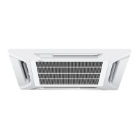
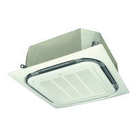
C Subclass:
Cassette
C: 3x3
06 Total cooling capacity (kW)
B Major model change
7 Minor model change
T Coil type:
T: 2-pipe
F: 4-pipe
V1 1 phase / 50 Hz / 220-240 V
B Produced in Europe
 Loading...