Installation EDUS39-600-F2_a
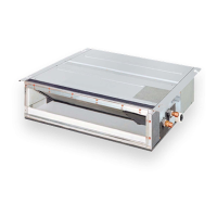
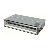
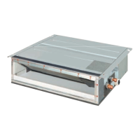
26 FXDQ-M
terminal board wiring to the outdoor unit and BS unit are
properly matched. If controls wiring and piping between the
outdoor and indoor units are mismatched, a communica-
tions malfunction is likely.
• Install a wiring interrupter or ground-fault circuit interrupter
for the power wiring.
• Make sure the ground resistance is no greater than 100Ω.
• To avoid short circuiting the power supply wire, be sure to
use insulated terminals.
• Do not turn on the power supply (wiring interrupter or
ground-fault circuit interrupter) until all other work is done.
DANGER
• Do not ground units to water pipes, telephone wires or light-
ning rods because incomplete grounding could cause a
severe shock hazard resulting in severe injury or death, or
to gas pipes because a gas leak could result in an explo-
sion which could lead to severe injury or death.
9-2 LIST OF STANDARD WIRING EQUIPMENT
NOTE
1. If the wiring is in a place where people it can be easily
touched, install a ground-fault circuit interrupter to prevent
electric shock.
2. When using a ground-fault circuit interrupter, make sure to
select one useful also to protection against overcurrent
and short-circuit.
3. When using a ground-fault circuit interrupter only for
grounding device, make sure to use a wiring interrupter
together.
• The length of the transmission wiring and remote controller
wiring are as follows:.
9-3 ELECTRICAL CHARACTERISTICS
MCA: Minimum Circuit Amps (A) MFA: Max. Fuse Amps (A)
KW: Fan motor output (kW) FLA: Full Load Amps (A)
10. WIRING EXAMPLE
10-1 HOW TO CONNECT WIRINGS
• Wire only after removing the control box lid as shown in
Fig. 14.
WARNING
• Use only specified wire and connect wires to terminals
tightly. Be careful that wires do not place external stress on
terminals. Keep wires in neat order so as to not to obstruct
other equipment. Make sure that the electric parts box lid
closes tightly. Incomplete connections could result in over-
heating, and in worse cases, electric shock or fire.
Power supply wiring
(including ground wire)
Transmission wiring
Remote controller wiring
Field fuses
Size Wire Size
15A
Must comply with
local codes.
2 conductor,
stranded copper,
non-shielded,
PVC or vinyl
jacket
AWG18
Outdoor unit – Indoor unit
Max. 3280 ft.
(Total wiring length: 6560 ft.)
Indoor unit – Remote controller Max. 1640 ft.
Units
Power sup-
ply
Fan motor
Model Hz Volts
Voltage
range
MCA MFA KW FLA
07 · 09 · 12 type
60
208-
230
Min. 187
Max. 253
0.9
15
0.062 0.7
18 type 1.3 0.13 1.0
24 type 1.4 0.13 1.1
Power supply wiring and
ground wire through conduit
Control box lid
Wiring Diagram
Fig. 14
(Rear)
∗
Do not connect power
supply wiring here.
That may cause
malfunctions.
∗Transmission wiring
∗Remote controller wiring
Clamp (for prevent slippage)
Clamp (for fixing in place)
Clamp the wiring sheaths (accessory (10))
Match up the wiring sheath with the fixing clasp with the clamping
material for preventing slippage on the power supply side and clamp
(accessory (9)).
Clamp
Inside unit
Outside unit
[How to adhere it]
Wire
(accsessory)
Sealing
material (12)
•Make sure to let a wire go through a wire penetration area.
•After wiring, seal the wire and wire penetration area to prevent
moisture and small creatures from the outside.
•Wrap the wire with the sealing material (12) as shown in the figure below.
(Otherwise, moisture or small creatures such as insects from
the outside may cause short-circuit inside the control box.)
Attach securely so that there are no gaps.
Penetration area
Screw
(accessory)
Conduit mounting
plate
(accessory)
Conduit
(field supply)
Power supply wiring and
ground wire through conduit
 Loading...